A Low-Profile Broadband Metasurface Antenna With Polarization Conversion Based on Characteristic Mode Analysis
 Jian Dong
 Rigeng Wu
 Yaxi Pan
- School of Computer Science and Engineering, Central South University, Changsha, China
In this paper, a low-profile, broadband metasurface antenna for polarization conversion is proposed based on characteristic mode analysis (CMA). A new type of metasurface unit with a partially chamfered symmetrical triangular structure is designed. The inherent physical characteristics of the antenna are analyzed based on CMA, and the expected characteristic modes are selected for excitation at a suitable position. Slot-coupled feeding via microstrip line realizes the performance of wide impedance bandwidth and axial ratio bandwidth (ARBW). The measured -10 dB impedance bandwidth of 36.3% (4.38–6.32 GHz) and the 3 dB ARBW of 20.1% (5.41–6.62 GHz) are achieved. The left-hand circular polarization (LHCP) is realized, and the measured highest gain in the working frequency band is 6.05 dBic. The overall size of the designed and fabricated metasurface antenna is 0.58
Introduction
In recent years, with the continuous development of wireless communication technology, the antenna as an important part of the communication system has attracted more and more scholars to invest in related research. The polarization mode of the antenna includes linear polarization (LP), circular polarization (CP), and elliptical polarization. With the advancement of communication technology, LP has been difficult to meet the modern complex communication environment, so the demand for CP is increasing [1]. CP has the properties of reducing multipath interference, polarization mismatch, and overcoming the Faraday rotation effect [2], and is widely used in communication equipment.
Traditional microstrip patch antennas are used in many scenarios because of their low profile, simple structure, easy fabrication, and easy integration [3–5]. However, as the requirements for antennas become higher and higher, microstrip patch antennas are difficult to meet the needs of modern communications because of their narrow impedance bandwidth and low gain. Metasurface antenna is expected to overcome such drawbacks as the traditional microstrip patch antenna. In recent years, metasurface antennas have been applied to CP antenna design by more and more scholars to improve the impedance bandwidth, axial ratio bandwidth (ARBW), and the gain of the antenna [6, 7]. In [8], a metasurface unit for polarization conversion was proposed, where the unit consisted of a hexagonal ring enclosed within a rectangular ring and printed on both sides of the dielectric substrate. Although the high gain was achieved, the impedance bandwidth and ARBW were both narrow. In [9], a metasurface antenna composed of square metal patch units was proposed, and four intersecting slots were used for slot coupling feed through the microstrip line. The antenna achieved the 3 dB ARBW of 14.5%, and the axial ratio beam bandwidth was more than 205°, but the impedance bandwidth of -10 dB was only 17%. In [10], a metasurface antenna with periodic elliptical patches rotated 45° to achieve polarization conversion was proposed. The antenna analyzed the principle of CP on the metasurface by using the equivalent circuit method. The antenna achieved the 3 dB ARBW of 17.4% and the peak gain of 8 dBic. But the size of the antenna was large and the -10 dB impedance bandwidth was only 20.6%. In [11], the metasurface unit composed of a split ring resonator and microstrip line was proposed, and the rotation angle between two adjacent units differed by 90°. Although a low radar cross-section and high gain were achieved, it had a narrow ARBW and a complex feed network. In [12], a metasurface CP antenna for 5G indoor applications was proposed, which was analyzed using transmission line and equivalent circuit models. The 2D meta-resonator construction and sloping slot coupled feeding achieved CP radiation, but its impedance bandwidth and ARBW were narrow. For the above-mentioned papers, some of them do not have an in-depth analysis to explain the inherent physical properties.
In recent years, characteristic mode analysis (CMA) has been used to analyze the inherent physical characteristics of the designed antenna and to gain a deep understanding of its working principle [13, 14]. Using CMA to analyze metasurface can well analyze its resonance characteristics and radiation characteristics, and obtain the best antenna performance through the analysis of each mode [15]. In [16], an H-shaped metasurface unit was proposed and the feed was slot-coupled through the cross-shaped aperture on the ground. Although CMA was used for the analysis, the paper mentioned did not consider the effects caused by the slot structure and did not analyze the results of modal weighting coefficient (MWC). In [17], a windmill-shaped metasurface unit was proposed to realize a reconfigurable tri-polarized antenna, and the 3 dB ARBW of 15% was obtained. The proposed metasurface structure was analyzed by using the modal significance and characteristic currents in CMA, but the principle of achieving CP was not analyzed in depth. In [18], a novel stereo metasurface unit was proposed, which effectively reduced the size and increased the bandwidth of the antenna. Although the resonant characteristics of the patch antenna and the metasurface were analyzed by CMA, only the modal importance was used for the analysis. However, CMA has several parameters available for antenna analysis, and it is difficult to characterize the antenna with one or two alone, and MWC as an important parameter is rarely analyzed.
In this paper, a new low-profile broadband metasurface antenna consisting of 4 × 4 partially chamfered symmetrical triangular structure units with a slot coupling feeding structure is proposed for a wide impedance bandwidth and ARBW. Different from most CMA-based designs where only the metasurface layer is analyzed, this paper also analyzes the effect of introducing a slot-coupled structure. In addition, the amplitude and phase of the MWC are analyzed to find the modes that are eventually excited and the modes that produce CP.
The rest of the paper is organized as follows. In Design and Analysis of Polarization Conversion Antenna, the metasurface antenna and the stepped slot patch antenna are introduced. At the same time, CMA is used to understand their resonance characteristics and radiation characteristics, and the final antenna design is given. In Results and Discussion, the designed metasurface antenna is fabricated, and its characteristics are measured and analyzed. In Conclusion, the conclusion of this paper is presented.
Design and Analysis of Polarization Conversion Antenna
Analysis of Proposed Antenna Based on CMA
CMA is a method of analyzing antenna without adding excitation, which is determined by factors such as antenna structure and size. There are three important parameters in CMA: eigenvalue (
To explain the working mechanism of the proposed metasurface antenna with polarization conversion, the CMA of the proposed metasurface antenna structure is carried out in the commercial software CST MWS 2021 to study its working characteristics. First, the multi-layer solver is used to analyze the CMA of the metasurface antenna from 3.5 to 7 GHz. The metasurface layer is composed of the upper metasurface and the underlying dielectric substrate, as shown in Figure 1. The substrate and ground are considered to be infinite. The material of the metasurface is Perfect Electric Conductor (PEC), and the dielectric substrate uses FR4 (
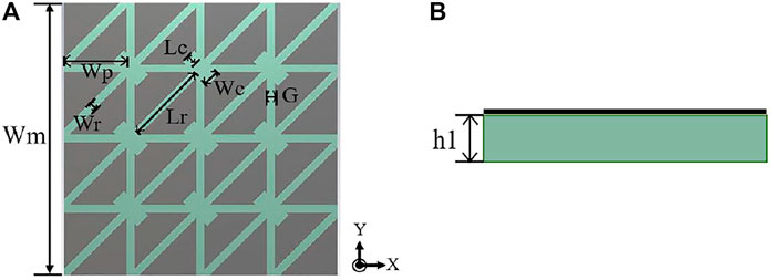
FIGURE 1. The structure of the metasurface layer: (A) Front view; (B) Side view.
The first four characteristic modes of the antenna are used for CMA at 5.8 GHz. Figure 2A shows the MS of the first four characteristic modes. It can be seen from the figure that the first three characteristic modes are close to 1 at 5.8 GHz, and Mode 4 is close to 1 at 6.7 GHz. The eigenvalues of each mode at the respective resonant frequency are close to 0 as shown in Figure 2B. The CAs of the four modes are shown in Figure 2C, and the difference between the CA of Mode 1 and Mode 4 is close to 90° at 5.8 GHz as shown in Figure 2D. To study the radiation characteristics, the characteristic current is analyzed. The characteristic currents of the four modes at 5.8 GHz are shown in Figure 3 and the arrow on the metasurface antenna represents the direction of the characteristic current. It can be seen from the figure that the current directions of Mode 1 and Mode 4 are orthogonal, and the maximum current distribution is concentrated at the center patch. The characteristic current direction of Mode 2 is mirror symmetry, and the characteristic current direction of Mode 3 is symmetric about the geometric center. Therefore, Mode 1 and Mode 4 are a pair of orthogonal modes due to the symmetry of the metasurface. It is possible to obtain CP by exciting with the same amplitude and a phase difference of 90°. If the excitation is added at the suitable location where the current is maximum, Mode 1 and Mode 4 can be excited at the same time to achieve CP.
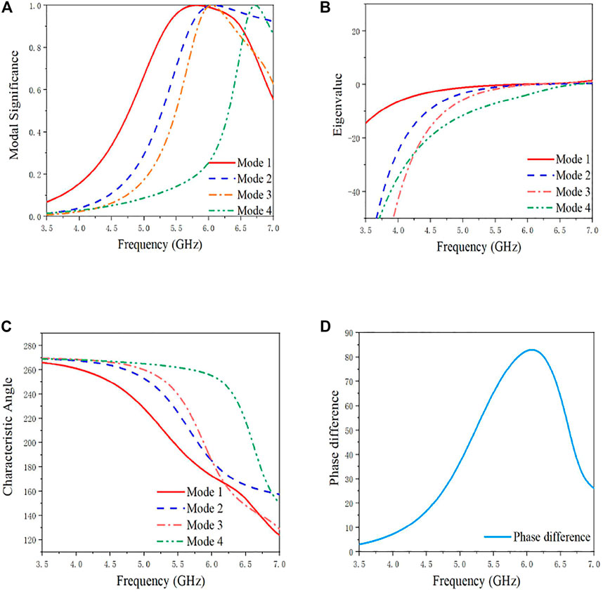
FIGURE 2. MS, eigenvalue, and CA of the metasurface layer and the difference between the CA of Mode 1 and Mode 4: (A) MS; (B) Eigenvalue; (C) CA; (D) Difference of CA.
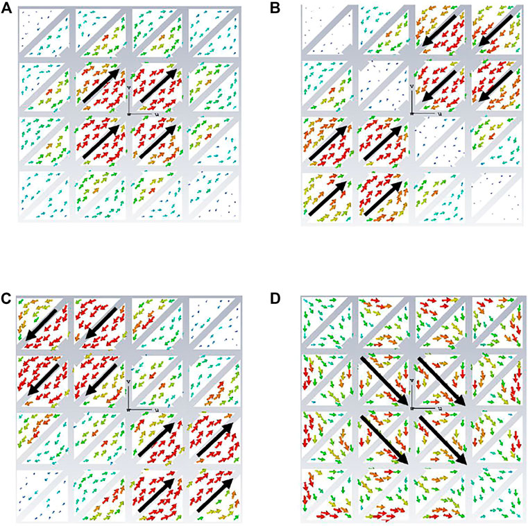
FIGURE 3. Characteristic current of the metasurface at 5.8 GHz: (A) Mode 1; (B) Mode 2; (C) Mode 3; (D) Mode 4.
CMA is performed on the stepped slot patch antenna, which structure is shown in Figure 4A. The first two characteristic modes of the stepped slot patch antenna are used for CMA. It can be seen from Figure 4B that the maximum values of the MS of the two modes are close to 1 at 4.25 GHz, and the potential bandwidth of the two modes greater than 0.707 is relatively narrow, which makes it difficult to achieve broadband. The characteristic currents of the two modes are shown in Figures 4C,D. Mode 1s is the main mode and its characteristic current is LP along the y-axis, while the characteristic current of Mode 2s has different directions so it is not representative and is ignored. Therefore, if the selected excitation location is appropriate, the stepped slot patch antenna can be excited to achieve LP along the y-axis.
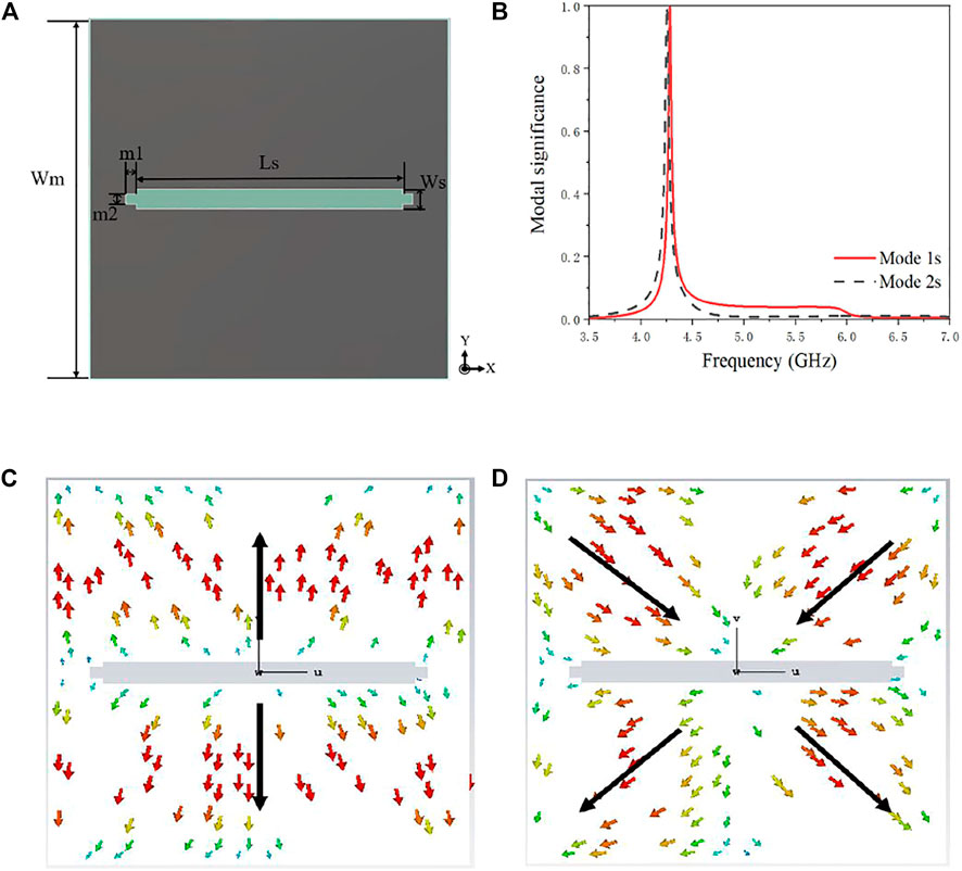
FIGURE 4. The structure, MS, and characteristic current of the stepped slot patch antenna: (A) Antenna structure; (B) MS; (C) The characteristic current of Mode 1s; (D) The characteristic current of Mode 2s.
CMA is used to analyze the overall structure of the antenna, and the results are shown in Figure 5. The first five most characteristic feature patterns are taken for analysis. From the MS in Figure 5A, it can be seen that Mode 0′ reaches 1 at 4.77 GHz, which satisfies the condition of resonance. The resonance frequency points of Mode 1′-Mode 3′ are all located at 5.5–6 GHz, and the resonance frequency point of Mode 4′ is 6.45 GHz. According to the results of the CMA performed on the slotted patch above, Mode 0′ is a characteristic mode introduced by the slotted patch, i.e., the slot mode, and the other four characteristic modes are the modes possessed by the metasurface. Figure 5B shows the eigenvalues corresponding to each characteristic mode and all of them reach 0 at their respective resonance points, satisfying the resonance condition. The CA of each characteristic mode is shown in Figure 5C, and the difference of CA between Mode 1′ and Mode 4′ is shown in Figure 5D. It can be seen that after the CMA of the overall structure of the antenna, the difference of the CA reaches 90°, and the structure has the condition to realize CP.
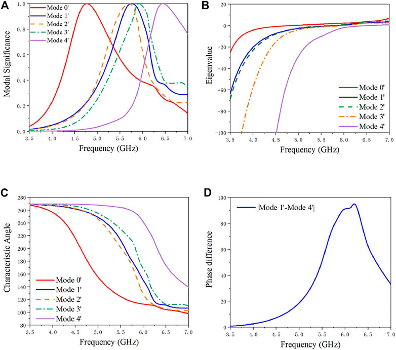
FIGURE 5. CMA of the overall structure: (A) MS; (B) Eigenvalue; (C) CA; (D) CA difference.
It is worth noting that the five modes are excited to some extent with the addition of the incentive structure. As can be seen in Figure 6A, the Mode 0′ is excited to a large extent, followed by the metasurface generated Mode 1′ and Mode 4'. Mode 2′ and Mode 3′ are also excited to some extent, but the degree of excitation is not high and the effect caused is small. The phases of the MWC of the five modes are shown in Figure 6B and the phase difference between Mode 1′ and Mode 4′ is shown in Figure 6C, and the results show that the antenna structure has the condition to achieve CP.
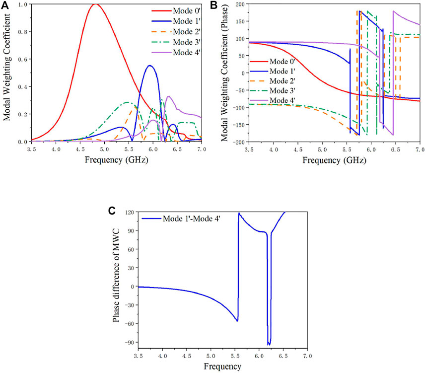
FIGURE 6. The result of MWC: (A) Magnitude of MWC; (B) Phase of MWC; (C) Phase difference of MWC.
Antenna Structure and Parameter Analysis
Through the above analysis of the inherent physical characteristics of the antenna using CMA, when the stepped slot patch antenna and the metasurface are excited at the same time, the conversion from LP to CP can theoretically be realized. The overall structure of the proposed metasurface antenna for converting LP to CP is shown in Figure 7. The geometry of the proposed antenna is composed of three metal layers and two substrate layers. The antenna consists of two layers of dielectric substrates with thicknesses of h1 and h2, respectively, and the material used is FR4 (
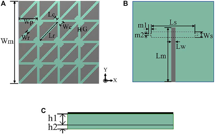
FIGURE 7. The overall structure of the CP metasurface antenna: (A) Top view; (B) Back view; (C) Side view.
By opening a stepped slot on the ground, the impedance matching and the ARBW can be better adjusted. The length m1 of the two steps on the ground will affect the impedance bandwidth and ARBW. As shown in Figure 8, when the other parameters remain unchanged, the parameter scan analysis is performed with m1 from 0.5 to 2.5 mm at intervals of 0.5 mm. It can be seen from the figure that the influence of m1 on the impedance bandwidth is not as great as the ARBW, and the impedance bandwidth is maintained at about 40%. However, for the ARBW, as the parameter m1 increases, the ARBW gradually becomes narrow, which will cause the performance of CP to deteriorate. Through comparative analysis, the final value of m1 is 1 mm. As shown in Figure 9, while keeping the other parameters unchanged, the interval of Ws from 1.0 to 3.0 mm is 0.5 mm for parameter scanning, and when Ws takes different values, the change of impedance bandwidth is greater than the impact on the ARBW. When the value of Ws is less than 2.0 mm, the impedance bandwidth and ARBW will become narrow, especially the impedance bandwidth. When Ws is 1.0 mm, the impedance bandwidth is only 19%, and the impedance bandwidth at this value is difficult to achieve broadband. At the same time, this value also narrows the ARBW, which makes it difficult to achieve the ideal CP effect. When the value of Ws is greater than 2.0mm, although the impedance bandwidth will be broadened, the ARBW will be affected. When the value of Ws is 3.0 mm, the ARBW is only 18%. Through comparative analysis, the final value of Ws is 2.0 mm.
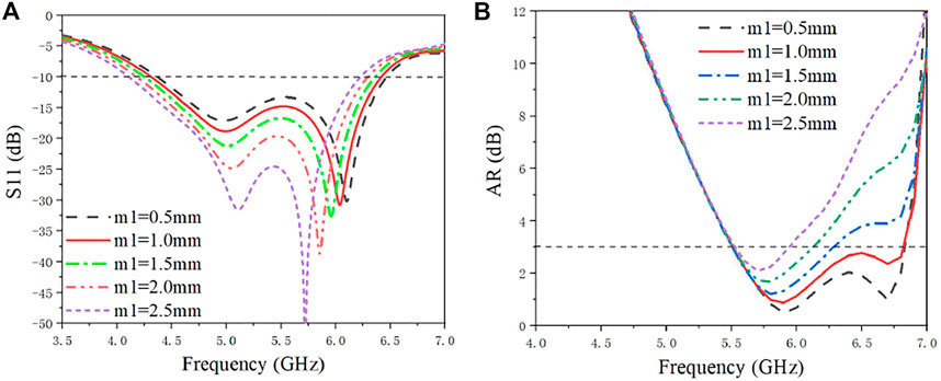
FIGURE 8. S11 and ARBW when m1 takes different values: (A) S11; (B) ARBW.
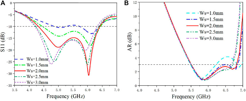
FIGURE 9. S11 and ARBW when Ws takes different values: (A) S11; (B) ARBW.
Based on the above analysis and optimization, other parameters of the metasurface antenna are shown in Table 1. By using the commercial software CST MWS for simulation optimization, the simulated impedance bandwidth of -10 dB is 39.33% (4.31–6.42 GHz), the ARBW of 3 dB is 21.25% (5.51–6.82 GHz), and the maximum gain is 6.25 dBic. The overall size of the proposed metasurface antenna is
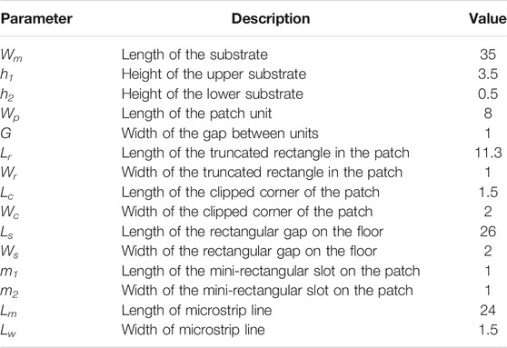
TABLE 1. Parameters of the proposed antenna (in millimeters).
Results and Discussion
In order to verify whether the performance of the designed antenna meets actual requirements, the designed antenna is fabricated and measured. The metasurface antenna is fabricated using a commonly used printed circuit board (PCB), as shown in Figure 10. Figure 11 illustrates the impedance bandwidth and ARBW obtained under simulation and measurement. The simulated −10 dB impedance bandwidth and 3 dB ARBW of the proposed metasurface antenna is 39.33% from 4.31 to 6.42 GHz and 21.25% from 5.51 to 6.82 GHz, respectively. The −10 dB impedance bandwidth and 3 dB ARBW of the fabricated metasurface antenna are 36.3% from 4.38 to 6.32 GHz and 20.1% from 5.41 to 6.62 GHz, respectively. Both the simulation and measurement results show that after the excitation is added, the mode of the stepped slot patch and the mode of the metasurface is excited at the same time, and the impedance bandwidth of the antenna is broadened. Figure 12 shows the gain and efficiency of the metasurface antenna under simulation and measurement. The maximum gain in the simulation and measurement are 6.25 dBic and 6.05 dBic, respectively, and the efficiencies in the simulation and measurement are 79.5 and 75.8%, respectively.
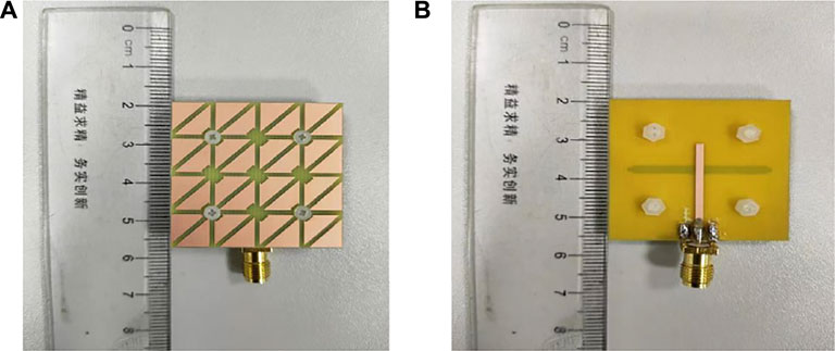
FIGURE 10. Fabricated photos of metasurface antenna: (A) Top view; (B) Rear view.
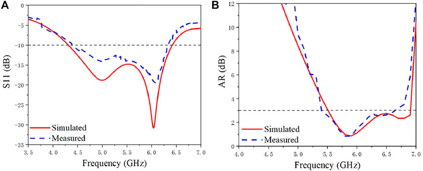
FIGURE 11. Simulation and measurement of the S11 and ARBW of the proposed antenna: (A) S11; (B) ARBW.
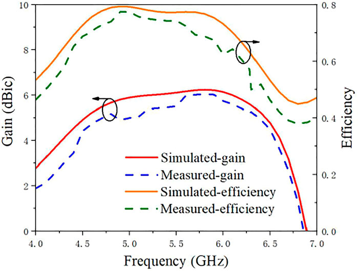
FIGURE 12. Simulation and measurement of the gain and efficiency of the proposed antenna.
Figure 13 shows the radiation patterns of the xoy-plane and yoz-plane at 5.8 GHz of the metasurface antenna under simulation and measurement. It can be seen from the figure that the simulated and measured radiation patterns are basically the same. In the xoz-plane and the yoz-plane, the measured LHCP levels are approximately from -3 dBic to 7 dBic, and the measured RHCP levels are approximately from -7 dBic to -18 dBic. In both the xoz-plane and the yoz-plane, the measured LHCP level is higher than RHCP, which means that the proposed metasurface antenna is an LHCP antenna. The simulation and measurement results show that the LP generated by the stepped slot patch is converted into CP after adding the metasurface layer, thereby realizing the polarization conversion. Due to the influences and limitations of manufacturing accuracy and measurement environment, the simulation results and the measurement results are different.
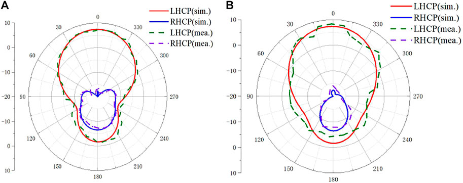
FIGURE 13. Comparison of simulated and measured radiation patterns at 5.8 GHz: (A) xoz-plane. (B) yoz-plane.
Table 2 summarizes the comparison of the performance of recently reported CP metasurface antennas in terms of measurement results. As can be seen from the table, the proposed antenna has the widest impedance bandwidth and ARBW. Although some designs have higher antenna gain than our design, they have a larger size. Also, the design and fabrication of some antennas are more complicated because of the including of the feeding network.
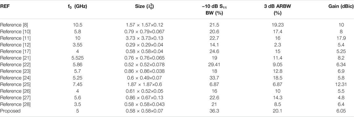
TABLE 2. Comparison of the performance of recently reported CP metasurface antennas.
Conclusion
In this paper, a novel low-profile broadband polarization conversion metasurface antenna using a partially chamfered symmetric triangular unit structure is proposed. The resonance characteristics and radiation characteristics of the metasurface antenna are analyzed by CMA, and the principle of polarization conversion is explained in depth. The slot-coupled feed through the microstrip line excites both the slot mode and the metasurface mode at the same time, which broadens the bandwidth of the antenna and realizes the polarization conversion. Simulated results show that the -10 dB impedance bandwidth and 3 dB ARBW of the proposed metasurface antenna are 39.33% (4.31–6.62 GHz) and 21.25% (5.51–6.82 GHz), respectively. By fabricating and measuring the antenna as verification, the measurement results show that the −10 dB impedance bandwidth of the proposed antenna is 36.3% (4.38–6.32 GHz), and the 3 dB ARBW is 20.1% (5.41–6.62 GHz). The measurement results and the simulation results are in good agreement. Moreover, the proposed antenna achieves a compact structure of only
Data Availability Statement
The original contributions presented in the study are included in the article/Supplementary Material, further inquiries can be directed to the corresponding author.
Author Contributions
JD and RW designed the structure and fabricated the sample. RW and YP performed the experiments. JD and RW wrote the manuscript with contributions from all the other authors. All authors participated in the discussion of the results.
Funding
This research was funded in part by the National Natural Science Foundation of China, grant number 61801521 and 61971450, in part by the Natural Science Foundation of Hunan Province, grant number 2018JJ2533, and in part by the Fundamental Research Funds for the Central Universities, grant number 2018gczd014 and 20190038020050.
Conflict of Interest
The authors declare that the research was conducted in the absence of any commercial or financial relationships that could be construed as a potential conflict of interest.
Publisher’s Note
All claims expressed in this article are solely those of the authors and do not necessarily represent those of their affiliated organizations or those of the publisher, the editors, and the reviewers. Any product that may be evaluated in this article, or claim that may be made by its manufacturer, is not guaranteed or endorsed by the publisher.
References
1. Dong J, Ding C, Mo J. A Low-Profile Wideband Linear-To-Circular Polarization Conversion Slot Antenna Using Metasurface. materials (2020) 13:1164. doi:10.3390/ma13051164
2. Liu S, Yang D, Pan J. A Low-Profile Broadband Dual-Circularly-Polarized Metasurface Antenna. Antennas Wirel Propag Lett (2019) 18:1395–9. doi:10.1109/lawp.2019.2917758
3. Malekpoor H, Hamidkhani M. Bandwidth and Gain Improvement for Reduced Size of Stacked Microstrip Antenna Fed by Folded Triangular Patch with Half V‐shaped Slot. Int J RF Microwave Computer‐Aided Eng (2021) 31:e22649. doi:10.1002/mmce.22649
4. Wan W, Xue M, Cao L, Ye T, Wang Q. Low‐profile Compact Metasurface‐loaded Patch Antenna with Enhanced Bandwidth. Microw Opt Technol Lett (2021) 63:2656–61. doi:10.1002/mop.32961
5. Xu KD, Zhu J, Liao S, Xue Q. Wideband Patch Antenna Using Multiple Parasitic Patches and its Array Application with Mutual Coupling Reduction. IEEE Access (2018) 6:42497–506. doi:10.1109/access.2018.2860594
6. Gao G, Zhang R-F, Geng W-F, Meng H-J, Hu B. Characteristic Mode Analysis of a Nonuniform Metasurface Antenna for Wearable Applications. Antennas Wirel Propag Lett (2020) 19:1355–9. doi:10.1109/lawp.2020.3001049
7. Supreeyatitikul N, Torrungrueng D, Phongcharoenpanich C. Quadri-Cluster Broadband Circularly-Polarized Sequentially-Rotated Metasurface-Based Antenna Array for C-Band Satellite Communications. IEEE Access (2021) 9:67015–27. doi:10.1109/access.2021.3075994
8. Swain R, Chatterjee A, Nanda S, Mishra RK. A Linear-To-Circular Polarization Conversion Metasurface Based Wideband Aperture Coupled Antenna. J Electr Eng Technol (2020) 15:1293–9. doi:10.1007/s42835-020-00402-z
9. Liu S, Yang D, Pan J. A Low-Profile Circularly Polarized Metasurface Antenna with Wide Axial-Ratio Beamwidth. Antennas Wirel Propag Lett (2019) 18:1438–42. doi:10.1109/lawp.2019.2919533
10. Yuan L, Yu‐Xuan H, Zhan‐Wei L, Shu-Ting C, Xiao-Ming X, Jing G. Design of a Compact Wideband CP Metasurface Antenna. Int J RF Microwave Computer‐Aided Eng (2020) 30:e22332. doi:10.1002/mmce.22332
11. Fan Y, Wang J, Li Y, Zhang J, Han Y, Qu S. Low-RCS and High-Gain Circularly Polarized Metasurface Antenna. IEEE Trans Antennas Propagat (2019) 67:7197–203. doi:10.1109/tap.2019.2920355
12. Wang Z, Liang T, Dong Y. Metamaterial‐based , Compact, Wide Beam‐width Circularly Polarized Antenna for 5G Indoor Application. Microw Opt Technol Lett (2021) 63:2171–8. doi:10.1002/mop.32866
13. Xu K-D, Luyen H, Behdad N. A Decoupling and Matching Network Design for Single- and Dual-Band Two-Element Antenna Arrays. IEEE Trans Microwave Theor Techn. (2020) 68:3986–99. doi:10.1109/tmtt.2020.2989120
14. Qas Elias BB, Soh PJ, Abdullah Al‐Hadi A, Vandenbosch GAE. Design of a Compact, Wideband, and Flexible Rhombic Antenna Using CMA for WBAN/WLAN and 5G Applications. Int J Numer Model Electron Networks, Devices Fields (2021) 34:e2841. doi:10.1002/jnm.2841
15. Liang Z, Ouyang J, Yang F. Design and Characteristic Mode Analysis of a Low-Profile Wideband Patch Antenna Using Metasurface. J Electromagn Waves Appl (2018) 32:2304–13. doi:10.1080/09205071.2018.1507843
16. Zhao C, Wang C-F. Characteristic Mode Design of Wide Band Circularly Polarized Patch Antenna Consisting of H-Shaped Unit Cells. IEEE access (2018) 6:25292–9. doi:10.1109/access.2018.2828878
17. Huang H, Wen H. Miniaturized Reconfigurable Tri‐polarization Metantenna Based on Characteristic Mode Analysis with High‐aperture Efficiency. Int J RF Microwave Computer‐Aided Eng (2021) 31:e22867. doi:10.1002/mmce.22867
18. Li X, Xi X, Yang X, Chen P, Wu R-X. Compact Patch Antenna Enabled by a Metasurface with Stereo Elements. Opt Express (2020) 28:38983–92. doi:10.1364/oe.412315
19. Mohanty A, Behera BR. CMA Assisted 4-port Compact MIMO Antenna with Dual-Polarization Characteristics. AEU - Int J Elect Commun (2021) 137:153794. doi:10.1016/j.aeue.2021.153794
20. Yan S, Vandenbosch GAE. Design of Wideband Button Antenna Based on Characteristic Mode Theory. IEEE Trans Biomed Circuits Syst (2018) 12:1383–91. doi:10.1109/tbcas.2018.2857466
21. Liu Y, Huang YX, Liu ZW, Cai ST, Xiong XM, Guo J. A New Broadband Circularly Polarized Antenna with a Single‐layer Metasurface. Int J RF Microwave Computer‐Aided Eng (2020) 30:e22226. doi:10.1002/mmce.22226
22. Rajanna PK, Rudramuni K, Kandasamy K. Characteristic Mode-Based Compact Circularly Polarized Metasurface Antenna for In-Band RCS Reduction. Int J Microwave Wireless Tech (2019) 12:1–7. doi:10.1017/s1759078719001119
23. Liang Z, Ouyang J, Yang F. Low‐profile Wideband Circularly Polarised Single‐layer Metasurface Antenna. Electron Lett (2018) 54:1362–4. doi:10.1049/el.2018.6790
24. Zhao W, Long L, Li Y, Xi C. Metasurface Superstrate Antenna with Wideband Circular Polarization for Satellite Communication Application. IEEE Antennas Wireless Propagation Lett (2016) 15:374–7.
25. Rajanna PKT, Rudramuni K, Kandasamy K. A High-Gain Circularly Polarized Antenna Using Zero-index Metamaterial. Antennas Wirel Propag Lett (2019) 18:1129–33. doi:10.1109/lawp.2019.2910805
26. Yue T, Jiang ZH, Werner DH. Compact, Wideband Antennas Enabled by Interdigitated Capacitor-Loaded Metasurfaces. IEEE Trans Antennas Propagat (2016) 64:1595–606. doi:10.1109/tap.2016.2535499
27. Hussain N, Naqvi SI, Awan WA, Le TT. A Metasurface‐based Wideband Bidirectional Same‐sense Circularly Polarized Antenna. Int J RF Microwave Computer‐Aided Eng (2020) 30:e22262. doi:10.1002/mmce.22262
Keywords: metasurface, characteristic mode analysis, polarization conversion, low-profile, broadband
Citation: Dong J, Wu R and Pan Y (2022) A Low-Profile Broadband Metasurface Antenna With Polarization Conversion Based on Characteristic Mode Analysis. Front. Phys. 10:860606. doi: 10.3389/fphy.2022.860606
Received: 23 January 2022; Accepted: 03 February 2022;
Published: 17 February 2022.
Edited by:
Kai-Da Xu, Xi’an Jiaotong University, ChinaReviewed by:
Haofeng Dou, China Academy of Space Technology, ChinaRong Jin, Huazhong University of Science and Technology, China
Copyright © 2022 Dong, Wu and Pan. This is an open-access article distributed under the terms of the Creative Commons Attribution License (CC BY). The use, distribution or reproduction in other forums is permitted, provided the original author(s) and the copyright owner(s) are credited and that the original publication in this journal is cited, in accordance with accepted academic practice. No use, distribution or reproduction is permitted which does not comply with these terms.
*Correspondence: Yaxi Pan, yaxipan@csu.edu.cn