Accurate Sensorless Multistable Microsystem With a Single Actuator
 Hussein Hussein
 Hossein Fariborzi
- ECE department, CEMSE division, King Abdullah University of Science and Technology, Thuwal, Saudi Arabia
A compact and monolithic multistable microsystem was developed to realize the accurate positioning on the microscale by using a single actuator, without any positioning sensors. The mobile part can be maintained in several stable positions at rest with accurate intermediate steps and a high stability margin at each position. Switching between stable positions can be performed in both directions on one axis by using a single actuator. Using the mechanical intelligence encoded in the internal mechanisms, the mobile part position can be switched one step forward or back to the initial position through a single activation of the actuator. Multistable devices were designed and fabricated based on the working principle, and their satisfactory operation, with effective holding at stable positions and switching in two directions, was experimentally demonstrated.
Introduction
Microdevices, such as various types of sensors, actuators, and micro-mechanisms, are being increasingly incorporated in advanced machines in all domains and different industrial and urban applications (Fitzgerald et al., 2021). The use of small devices can promote the incorporation of higher functionalities in smaller spaces. Consequently, many miniature devices have been developed, the performance of which exceeds that of the macroscale counterparts. Nevertheless, the design of microdevices involves several limitations and the corresponding miniaturization is challenging. Innovative approaches and more intelligent structures are required to develop compact devices and facilitate miniaturization.
Microdevices are generally based on multiphysics phenomena, and their design requires expertise in various domains. The materials and fabrication processes are intricately involved in the design (Ananthasuresh, 2021). Moreover, the assembly is limited at this scale, and commonly used microfabrication techniques impose a planar and monolithic constraint on the structure. Mechanisms, which usually consist of an assembly of rigid elements with articulated joints on the macroscale, are replaced by compliant mechanisms on the microscale. Furthermore, on the microscale, the force balance is dominant for linear and surface forces (such as forces related to the surface tension and electrostatic, magnetic, thermal, and friction effects) instead of the volume forces (such as forces related to the mass, inertia, combustion, and buoyancy effects) that are dominant at the macroscale. Smart materials, such as piezoelectric materials, pyroelectric materials, shape-memory alloys, and active polymers, which can deform or generate an electrical signal in response to an external stimulus, and linear/surface force-based transducers (such as electrostatic and electrothermal) are commonly used at the microscale owing to their compatibility with the microtechnology constraints.
Notably, the accessibility to microdevices is limited. The inspection and manipulation on the small scale require specific tools and advanced measurement systems. The control of an autonomous micro-electromechanical system (MEMS) requires either external sensors or built-in microfabricated sensors for feedback. However, external sensors are bulky and reduce the capacity of miniaturization. In addition, the incorporation of built-in sensors in the monolithic structure of the microsystem complicates the design and fabrication and induces limitations in terms of the control and performance.
Digital microbotics represents a micropositioning approach, which exploits the accuracy of stable positions in multistable mechanisms to design accurate and discrete micropositioning systems. Internal (such as electrostatic and piezoresistive sensors) and external (such as cameras with microscopes and interferometers) position sensors do not need to be used to monitor the positioning accuracy in multistable mechanisms. The elimination of sensors simplifies the device structure and enhances the control and power delivery schemes. Such frameworks can enable more efficient miniaturization and operation in small environments and enclosed spaces (Chen et al., 2011; Chalvet et al., 2013; Hussein, 2015; Hussein et al., 2018; Mohand-Ousaid et al., 2021).
Apart from the feedback realization, the dexterity in actuation is a key limitation for the miniaturization of microsystems with mobile parts. Actuators implemented on both the large and small scale usually generate motion for one mobile block in one degree of freedom (DOF) and one direction. Additional mechanisms must be implemented with the actuator to transmit the motion to other mobile parts, thereby enabling motion in multiple DOFs and/or multiple directions. A relevant example for the large scale is the motor of a car, which is implemented with a transmission system to transmit the motor axis rotation to the wheels, a steering system to allow left and right movement (increase in the DOFs), and a gearbox to allow movement at different speeds and reversal of the direction of motion. The microfabrication limitations and complexity of assembly at the microscale limit the design of such mechanisms. Thus, an actuator is typically employed in microsystems to move one mobile block in one direction, and multiple actuators must be used to move several components in multiple directions in advanced microsystems. To overcome the challenges associated with miniaturization, innovative mechanisms must be developed to increase the dexterity of actuators and reduce their numbers in microsystems.
Considering this aspect, this paper proposes a sensorless and monolithic multistable microsystem with a compact stepping mechanism. As compared with other multistable microsystems (Chalvet et al., 2013; Hussein et al., 2018; Hwang and Arrieta, 2018; Hua et al., 2019; Zanaty et al., 2019; Gorissen et al., 2020; Jeong et al., 2020; Ramakrishnan and Frazier, 2020; Mohand-Ousaid et al., 2021) and stepping actuators (Pai and Tien, 2000; Yeh et al., 2002; Tas et al., 2003; De Boer et al., 2004; Maloney et al., 2004; Oak et al., 2011; Penskiy and Bergbreiter, 2013; Contreras and Pister, 2017), the novel design of the multistable microsystem exploits the advantages of digital microbotics, in which the mobile part can be accurately placed at multiple stable positions without implementing sensors. Furthermore, the actuation dexterity is enhanced by using only a single actuator to move the mobile part in two directions and hold it in multiple stable positions. The switching between stable positions is based on the stepping principle in one direction and direct movement to the initial position in the other direction. In addition to alleviating the miniaturization limits, the use of a single actuator simplifies the control to a basic level (on-off scheme), reduces the complexity of the electronics and power supply, and enables fast switching compared to multistable microsystems and stepping motors based on multiple actuators.
Working Principle
Digital micropositioning requires performing two main functions: holding and switching (Hussein, 2015). Holding is performed either actively, using an actuator to hold the mobile part at discrete positions, or passively, using the potential energy of deformable structures (Cao et al., 2021) or magnetic materials (Petit et al., 2014). The stable positions can be categorized based on their level of holding: A stable position is “free” when it changes with a slight external force or disturbance and “maintained” when it does not change unless an external force, exceeding a certain barrier (known as the holding force), is applied. The margin of stability is proportional to the holding force. The switching function is performed using actuators, which break the holding at stable positions and move the mobile part to other stable positions in a discrete workspace.
Multistable devices are increasingly implemented in novel applications, such as surgery tools (Zanaty et al., 2019), drug delivery (Salem et al., 2018), space applications (Zirbel et al., 2016), metamaterials (Ramakrishnan and Frazier, 2020), robotics (Gorissen et al., 2020), energy harvesters (Hwang and Arrieta, 2018), sensors (Frangi et al., 2015), and actuators (Hussein et al., 2018). Bistability represents the simplest case of multistability, and thin beam bistable mechanisms, with curved or inclined forms, are the most commonly used types of bistable mechanisms in microsystems (Hussein et al., 2015; Hussein et al., 2019; Hussein et al., 2020c; Hussein et al., 2020b; Hussein and Younis, 2020; Cao et al., 2021). Multistable micro-mechanisms are based on the assembly of elementary mechanisms with a small degree of multistability, either in series (Gerson et al., 2012; Zhang et al., 2015) or parallel (Chalvet et al., 2013; Che et al., 2016; Hua et al., 2019; Mohand-Ousaid et al., 2021), or on a mobile part actuated based on stepping mechanisms (Arthur et al., 2011; Hussein et al., 2018).
The first proof of concept for digital micropositioning corresponded to a bistable module with a simple structure (Chen et al., 2011; Hussein et al., 2014). Multiple bistable modules were introduced in parallel in a complete monolithic microsystem to switch a mobile part between multiple stable positions in a planar discrete workspace (Chalvet et al., 2013). Moreover, a multistable module based on the stepping principle was developed to replace all the bistable modules in the previous design (Hussein, 2015; Bouhadda et al., 2018; Hussein et al., 2018; Mohand-Ousaid et al., 2021). Notably, the use of multistable modules based on the stepping principle increased the number of stable positions, decreased the size of the structure and number of internal components, increased the accuracy of stable positions, and enabled more robust fabrication, easier control, and faster switching with a lower energy consumption. However, several actuators were required to perform the switching in each module (four and six actuators in the bistable and multistable modules, respectively).
This paper proposes a multistable microsystem based on the stepping principle and a single actuator to perform switching. Figure 1 illustrates the working principle for the multistable microsystem. The microsystem consists of several mechanisms that interact simultaneously and/or sequentially to hold and switch the mobile part between several stable positions. These mechanisms include a mobile part, one actuator, an actuator shuttle, two grippers, and the springs connected to the grippers and mobile part.
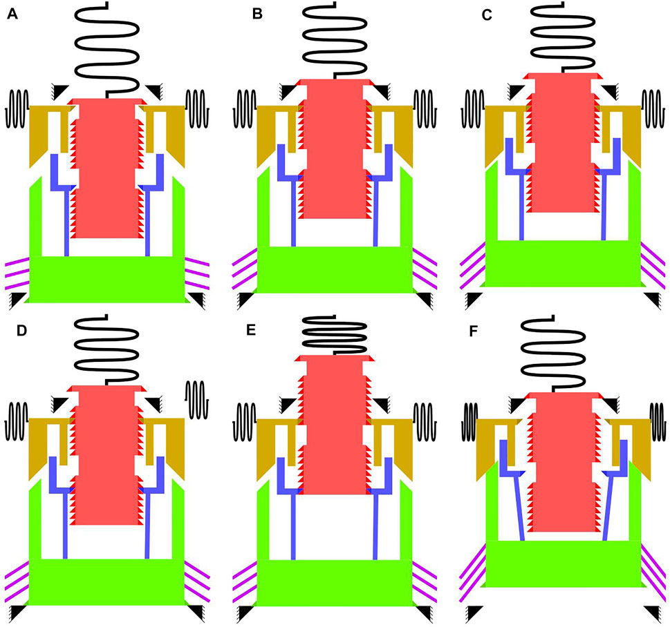
FIGURE 1. Working principle for the multistable microsystem, consisting of a mobile part (red), actuator (purple), actuator shuttle (green), top gripper (yellow), bottom gripper (blue), and springs connected to the grippers and mobile part: (A) as-fabricated configuration; (B) armed configurations at the initial position; (C) configuration when the actuator is activated at a low level to move the mobile part one step up; (D) configuration at the second stable position when the actuator is deactivated; (E) configuration after several upward steps are implemented until the last stable position; (F) configuration when the actuator is activated at a high level to open both grippers, and the mobile part returns to the initial position.
The mobile part is connected to a spring mechanism that guides its displacement in the vertical direction and applies a restoring force downward after displacement. The mobile part is held and manipulated by engaging its side teeth with the grippers. The top gripper is connected to two spring mechanisms (one for each jaw), which guide the horizontal displacement while opening and closing and apply a restoring force to engage the teeth with the mobile part. The bottom gripper can be also opened and closed horizontally. They are attached to the actuator shuttle at the bottom. The actuator shuttle is connected to a V-shaped electrothermal actuator, which controls the vertical displacement of the shuttle. Activating the actuator pushes the shuttle upward, and deactivating it returns the shuttle to the bottom position owing to the restoring force of the actuator.
Arming
After fabrication, the mobile part and shuttle are armed, as shown in Figure 1B. The arming is performed by manually moving the mobile part and shuttle beyond the stop blocks (black teeth). The stop blocks restrain the mobile part and shuttle from moving back to their as-fabricated positions after arming. Furthermore, arming helps engage the teeth between the grippers and mobile part. The teeth profiles between the mobile part and grippers are oriented to release both parts when the balance of the vertical forces applied on both parts is dominant in one direction and to engage both parts when the balance is dominant in the opposite direction.
In addition, arming adds restoring forces from different components that undergo deformation, i.e., springs of the mobile part and top gripper, structure of the bottom gripper, and actuator. These restoring forces are applied to the rigid mobile components connected to the deformable parts, i.e., the mobile part, gripper tip, and actuator shuttle.
Holding Mechanism at Rest
The restoring forces applied on the different components are of significance to the functioning of the multistable system. In particular, the restoring force of the actuator is directed downward, and it maintains the shuttle in the bottom position at rest, with the shuttle being in contact with the bottom stop-block. The restoring forces applied on both grippers engage them with the mobile part. The restoring force applied on the mobile part is directed vertically toward the contact with the top stop-block. The restoring force directions and teeth orientations facilitate the engagement of the teeth of the mobile part and grippers at rest and do not allow the mobile part from moving backward to the as-fabricated position when engaged with the grippers.
In other words, the mobile part is in a stable position at rest when the shuttle is in contact with the bottom stop-block, and the teeth of grippers are engaged with certain teeth of the mobile part in the locked state.
Switching Mechanism
The actuator is activated for a short period at two levels of power to switch the mobile part up or down. The first level is sufficient to move the shuttle with the mobile part one step upward. For the second level, the driving force of the actuator is adequately large to move the shuttle upward until it contacts the top gripper and opens both grippers. Activating the actuator at the first and second levels allows upward and downward switching, respectively.
Switching Upward: Stepping Principle
The vertical force applied by the actuator is higher than the restoring force of the mobile part. When the actuator is activated at the first level, the driving force of the actuator is sufficient to release the top gripper, move the shuttle with the mobile part one step upward, and reengage the top gripper with the next lower pair of teeth in the mobile part (Figure 1C). When the actuator is deactivated, the restoring force of the actuator is sufficient to release the bottom gripper, move the shuttle backward until it contacts the bottom stop-block, and reengage the bottom gripper with the next lower pair of teeth in the mobile part.
In this manner, the mobile part switches up one step when the actuator is activated and deactivated at the first level. By repeating the activation at the first level, the mobile part can be moved by the desired number of steps. Figures 1D,E show the mobile part at rest in the second and last stable positions, respectively. The distance between the stable positions is equivalent to that between the teeth on the mobile part, which is, to a large extent, independent of the fabrication tolerances (Hussein et al., 2017). Therefore, the distance between the stable positions is reasonably accurate.
Switching Downward: Return to the Initial Position
The mechanism enabling the use of a single actuator for both upward and downward switching is based on the distance traveled by the actuator at the two input power levels. At the first input level, both grippers are not opened simultaneously, and one step upward can be implemented by deactivating the actuator, as mentioned previously. At the second input level, the shuttle moves farther, leading to several interactions between the shuttle, top gripper, and bottom gripper during the displacement. At this power level, the actuator pushes the shuttle up until it contacts the top gripper. The top gripper opens horizontally while the shuttle is moving up, and the top gripper subsequently starts to open the bottom gripper as well. When both grippers are completely open and disengaged from the mobile part, as shown in Figure 1F, the mobile part returns to the first position owing to the restoring forces of the spring. The actuator can be then deactivated to return the grippers to their rest position.
Multistable Microsystem Design
The multistable microsystem design is aimed to incorporate the holding and switching functions, as clarified in the working principle. Figure 2 presents the layout for the multistable microsystem. The different components of the multistable systems are fabricated in the same monolithic layer and are based on deformable structures. These components are symmetric with respect to the middle vertical axis of the multistable system. This configuration helps guide the vertical displacement of the actuator shuttle and mobile part.
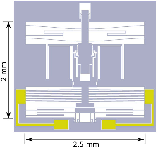
FIGURE 2. Layout of the multistable microsystem.
Arming
Figure 3 shows the as-fabricated configuration for the bottom stop-block (Figure 3A), top stop-block (Figure 3B), and left side of the gripping area (Figure 3C). The grippers on the right side are symmetrical to those on the left side. Figures 3D–H show the distances between components relevant to the operation of the multistable microsystem.
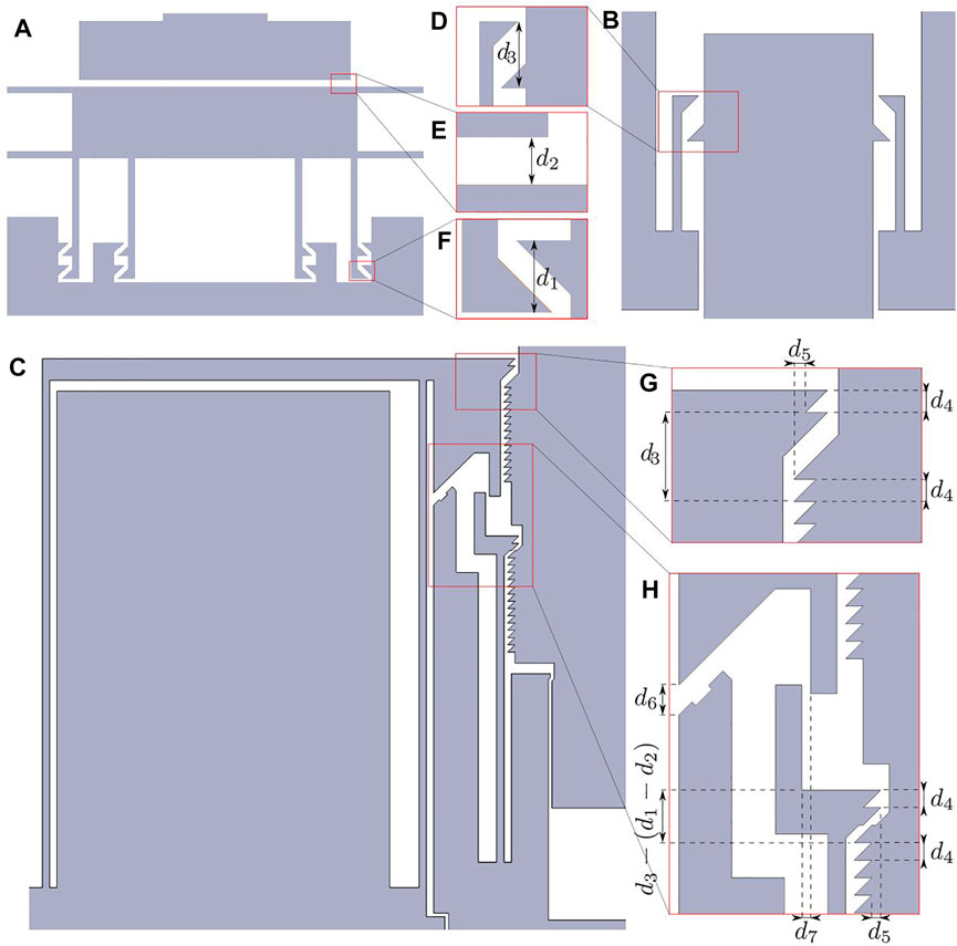
FIGURE 3. As-fabricated configuration in the (A) bottom stop-block area, (B) top stop-block area, and (C) on the left side of the gripping area. Magnified view of the distances between (D) teeth at the top stop-block, (E) bottom stop-block and shuttle, (F) teeth at the bottom stop-block, (G) teeth at the top gripper, and (H) interaction area between the gripper jaws and shuttle.
In the arming phase, the bottom stop-block is moved up a distance d1 to engage the teeth (Figure 3F). Consequently, the actuator shuttle is pushed upward by a distance d1-d2 (Figure 3E). The flat surface for the bottom stop-block helps ensure a stable contact with the shuttle after activating and deactivating the actuator. The stop block is held using S-springs to reduce the force applied on the teeth after arming.
Later, the mobile part is armed by moving it upward by a distance d3 to engage with the top stop-block (Figure 3D). This configuration ensures that the mobile part does not return to the as-fabricated position after arming. Moreover, the mobile part is engaged with the top gripper (Figure 3G) and bottom gripper (Figure 3H). Both grippers open horizontally at a distance d5 at their tips after arming to add horizontal restoring forces in the locking state of the grippers (Figures 3G,H).
In the different cases, several pairs of teeth are simultaneously engaged at the stop blocks, grippers, and mobile part to reduce stress and avoid failure. The teeth are horizontally aligned on one side to limit the displacement in one direction and inclined 45° from the other side to allow the release of the engaged components while moving in the other direction. Figure 4 shows the bottom stop-blocks and gripping area after arming.

FIGURE 4. Configurations after arming for the (A) bottom stop-block, (B) top stop-block, (C) and gripping area.
Switching
The interaction between the components of the multistable system mainly occurs in the gripping area during switching. The bottom gripper has a simple structure, with each jaw consisting of a single beam with a pair of teeth at its top end. This beam can undergo horizontal deformation while interacting with the teeth of the mobile part or top gripper. The teeth on the jaw are close to the beam axis. Thus, the teeth displacement can be considered horizontal to a certain extent for a limited deformation of the beam.
The jaw of the top gripper has a parallelogram structure, with two parallel deformable beams connected to a thicker beam at the top. This mechanism allows the top beam to undergo only horizontal displacement, with a pair of teeth placed at its end. The teeth are relatively far from the axis of the first deformable beam. Thus, the parallelogram mechanism is selected as it can support the relatively high vertical forces from the mobile part at the teeth level while allowing only horizontal displacement for the gripper.
Two channels are designed to guide the vertical displacement of the shuttle and mobile part. The first channel is located between the mobile part and shuttle, and the second channel is located between the shuttle and external structure, as shown in Figure 2. The allowance in each channel is only 2 μm on both the left and right sides. These channels are crucial to ensure the functioning of the multistable system. Without this constraint, the shuttle may stitch with the mobile part on one side while opening and closing the grippers, which can tilt the mobile part and shuttle. This issue led to the failure of several multistable prototypes developed before the final design presented in this paper.
The V-shaped actuator is the driving component in the multistable microsystem. In particular, the V-shaped actuator is considered suitable for this application because of its compactness and simple design, monolithic and compliant structure, compatibility with microfabrication techniques, large force and displacement range consistent with the range required for this application, guided lateral displacement for the mid-shuttle, low driving voltage, reliability, long lifetime, and robust structure, which can decrease the chances of failure at the actuator level [compared to the U-shaped actuator (Hussein et al., 2018)]. The V-shaped actuator is activated by applying a voltage difference on the two boundaries. The current passing through the thin beams of the actuator results in the length expansion of the beams due to Joule heating, and the lateral displacement is amplified at the midpoint of the thin beams, at which the shuttle is connected.
The step between subsequent stable positions and teeth dimensions are equal to d4 (Figures 3G,H). To switch upward, the actuator is activated to move the shuttle upward to a distance larger than d4+d1-d2 (at which the top gripper engages with the next pair of teeth on the mobile part) but smaller than d6+d5 (at which both grippers are contact). The mobile part switches one step upward after deactivating the actuator, as clarified in the working principle.
To switch downward, the actuator pushes the shuttle upward by a distance d6 before contact with the top gripper (Figure 3H). The contact faces on both sides are inclined 45°. Therefore, the shuttle moves up after contact, while the top gripper opens horizontally with a similar distance. When the shuttle moves up by a distance d6+d7+d5, the jaws of the top gripper open horizontally to a distance d5+d7, at which they contact the jaws of the bottom gripper [which are already opening with a distance d5 after arming in the locking state (Figure 3H)]. The contact faces between the top and bottom grippers are vertical and parallel, thereby enabling both grippers to open simultaneously after contact. Subsequently, the shuttle moves up beyond a distance d6+d7+d4+d5, at which the top and bottom gripper jaws open more than d7+d4+d5 and d4+d5, respectively. At this level, both grippers open, and the mobile part is released from the grippers. Subsequently, the mobile part moves to the initial position due to restoring forces where it contacts the top stop-block. After deactivating the actuator, the grippers return to their rest position, as clarified in the working principle. The distances d1–d7 considered in the design are listed in Table 1.
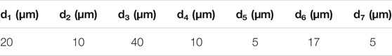
TABLE 1. Distances d1, d2, d3, d4, d5, d6, and d7 considered in the design of the multistable microsystem.
Force Equilibrium
The force equilibrium facilitates the holding of the mobile part at stable positions and switching between stable positions. The top part of the multistable system contains a constant-force mechanism as the spring mechanism for holding and guiding the mobile part displacement. This mechanism consists of two curved beams and one S-shaped beam (Figure 2). The curved beam is widely used in MEMS as a bistable mechanism (Hussein et al., 2019; Hussein and Younis, 2020) and exhibits several advantages relevant to this application, such as a simple and monolithic structure, rectilinear lateral guidance for the middle shuttle displacement, large displacement range, and negative stiffness behavior between the two stable positions. Moreover, the S-shaped beam can undergo a large displacement while exhibiting only positive stiffness behavior.
The combination of the curved and S-shaped beams having similar stiffness amplitudes with opposite signs results in a constant-force behavior over a relatively large range of displacement (Wang and Xu, 2018; Zhang et al., 2018). Thus, in addition to the vertical guidance over this displacement range, the constant-force mechanism helps ensure nearly similar force and stability conditions over different stable positions. Figure 5A shows the force-displacement curve for the constant-force mechanism. A constant force of nearly 2 mN is applied on the mobile part after arming, for a maximum displacement of more than 120 μm. The stable positions of the multistable system are designed in this range of displacement.
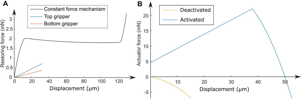
FIGURE 5. Force–displacement curves for the (A) constant-force mechanism and top and bottom grippers and (B) actuator when it is at rest and activated at the maximum voltage.
The bottom and top grippers have restoring forces that are imposed on the mobile part in the locking direction to engage both parts. Figure 5A shows the force-displacement curves for a single jaw of the grippers. As shown in Figure 5A, the jaws of the bottom and top grippers engage with the mobile part with a force of 0.06 and 0.12 mN in the closing state, respectively (when both grippers open at a distance d5 = 5 μm). These jaws require a horizontal force of at least 0.18 and 0.36 mN to release the teeth from the mobile part (when both grippers open for a distance larger than d4+d5 = 15 μm). At the second activation level, the bottom and top grippers are opened horizontally through the shuttle for at least 15 and 20 μm (d7 = 5 μm), respectively. Considering the force curves, a horizontal force of at least 1.33 mN is required to open both grippers until the threshold to release the mobile part. Notably, the curves in Figure 5A are obtained based on finite element simulations performed on ANSYS for the three mechanisms. The finite element simulations are based on static analysis using planar structural elements (Plane 82). The restoring forces are obtained in separate simulations for each mechanism after fixing boundaries and imposing displacement on the mid-shaft of the constant force mechanism (mobile part) and the tip of the grippers.
The behavior of the V shape actuator is thoroughly investigated in the literature. The analytical model in (Hussein et al., 2020a; Hussein et al., 2020d) considers electrothermal axial loading, lateral force, and different cases of buckling, and showed very good agreement with finite element simulations and experimental measurements. Figure 5B shows the force-displacement curves for the actuator at rest and when activated at the maximum voltage. The curves are determined based on the analytical equations in (Hussein et al., 2020a; Hussein et al., 2020d) relating the force, displacement, and input voltage of the actuator. The forces are positive when the actuator pushes the shuttle upward and negative in the opposite direction. The zero displacements in the curves shown in Figure 5 correspond to the as-fabricated positions of the mobile components. The material properties considered in the determination of these curves pertain to the silicon material in the fabricated device.
The restoring force of the actuator (after deactivation) moves the shuttle downward to its rest position (at which the shuttle contacts the bottom stop-block). Specifically, when deactivated, the actuator pushes the shuttle down with a force of at least 3.5 mN (for an actuator displacement higher than d1-d2 = 10 μm), as shown in Figure 5B. This force is sufficient to open the bottom gripper through the contact at the teeth level while moving the shuttle downward (considering friction forces at the inclined faces of the teeth).
The mobile part at rest is prohibited from moving downward owing to the contact with the bottom gripper, shuttle, and bottom stop-block, and from moving upward due to the restoring force from the constant-force mechanism (∼2 mN). To overcome the holding force at rest, an upward force from the actuator, larger than the restoring force from the constant-force mechanism, must be provided, to open the top gripper through the contact at the teeth level.
The actuator moves for around 20 μm (d4+(d1-d2)) and 37 μm (d6+d7+d4+d5) to perform the upward and downward switching, respectively. According to the “Activated” curve in Figure 5B, the forces that can be generated from the actuator at these distances (13.9 mN at 20 μm and 21.8 mN at 37 μm) are higher than the force required to drive the shuttle upward. The maximum voltage considered in the “Activated” curve in Figure 5B is determined for a maximum temperature of 600°C.
Results and Discussion
Fabrication
Figure 6A shows the scanning electron microscopy (SEM) image for a microfabricated multistable microsystem based on the proposed design. The multistable microsystem is fabricated on silicon-on-insulator (SOI) wafers, following the fabrication process shown in Figure 6B. The SOI wafers have device, oxide, and handle layers with 25 μm, 2 μm, and 300 μm thicknesses, respectively [Figure 6(B1)]. The mobile components of the device are fabricated in the top device layer. The handle layer serves as a support for the fixed parts in the device. The buried oxide layer helps release the mobile parts and ensures electrical separation between the different components.
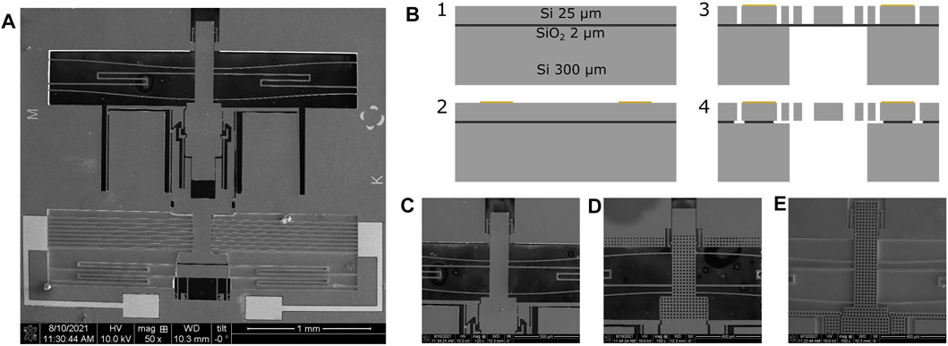
FIGURE 6. (A) SEM image for the microfabricated multistable microsystem. Fabrication process based on SOI wafers. (B1) The SOI has device, oxide, and handle layers with thickness values of 25 μm, 2 μm, and 300 μm. (B2) A metal layer is first deposited and patterned. (B3) The device and handle layers are etched using DRIE. (B4) The device is released from the oxide via HF wet etching. SEM images for the mobile part in microfabricated multistable microsystems, in which (C) the backside is completely etched, (D) the backside is partly etched at the edges and the remaining part is removed during releasing, (E) the backside is neither etched nor removed.
A chromium/gold metallic layer (50 nm/200 nm) is firstly deposited on top of the wafer and then patterned using photolithography and metal-wet etching [Figure 6(B2)]. This layer provides the electrical connectivity for the actuator at the pad level. A photoresist mask is then deposited and patterned on top of the device layer using photolithography, and the device layer is etched using deep reactive ion etching (DRIE). Afterward, a chromium layer is deposited on the handle layer and used as a hard mask for the handle layer etching using DRIE [Figure 6(B3)]. The chromium hard-mask is patterned using photolithography and metal-wet etching. In the last step of fabrication, the buried oxide layer between the openings in the device and handle layer is etched by wet HF to release the mobile parts in the microsystem [Figure 6(B4)].
Figures 6C–E show three configurations for the fabricated devices. In the first configuration (Figure 6C), the handle layer behind the mobile parts is completely etched to release the large mobile components from the backside in the last fabrication step. In the second configuration (Figure 6D), the large block is released simultaneously from the device and handle layers after etching the edges of this block in the device and handle layers. This configuration helps reduce the etching area and enhances the robustness of the fragile components in large openings (Sari et al., 2012; Hussein et al., 2018). In the third configuration (Figure 6E), the mobile components are released only from the openings in the device layer, and the handle layer is not etched.
Experiments
The microfabricated multistable devices are tested under a probe station, as shown in Figure 7A. Two probe needles are used to supply the power and realize manipulation. The probes are connected to a power supply to apply constant voltages on the actuator and activate it at two levels, as explained in the working principle.
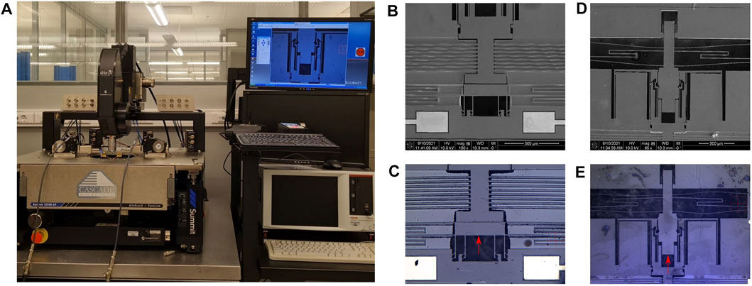
FIGURE 7. (A) Probe station used in the experiments for power supply and micromanipulation via probe needles under a microscope. (B) SEM image of the as-fabricated bottom stop-block. (C) Optical image of the armed configuration of the bottom stop-block. (D) SEM image for the as-fabricated top stop-block. (E) Optical image of the armed configuration of the top block-part in a multistable microsystem.
The multistable device is manually armed using probe needles, as shown in Figures 7C,E. The shuttle is first armed by pushing the bottom stop-block upward until it engages with the teeth (Figure 7C). Subsequently, the mobile part is armed by pushing upward until it engages with the teeth on the grippers and top stop-block (Figure 7E). The probe needle may push the mobile part several steps during arming as there are no stoppers in the arming direction.
After arming, the multistable devices can be switched between stable positions by applying constant voltages on the actuator for a short period. A switching step is implemented in two subsequent phases: activation and deactivation. Switching can be performed in two directions by applying voltages at two levels on the actuator, as explained in the working principle. Figure 8 shows the optical images for the functioning of the multistable system while implementing switching in the two directions. The images correspond to the same location in the gripping area. The optical images in Figure 8A are relative to the voltage activation levels shown in Figure 8B. Two red lines are placed as references, reflecting the displacement for the shuttle and mobile part in different phases.
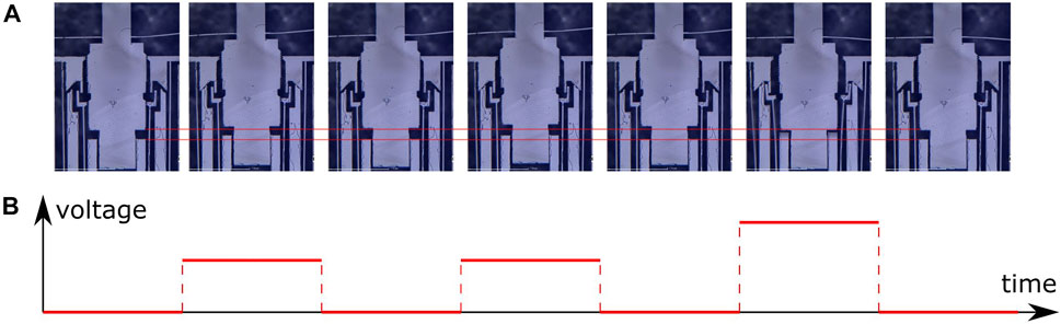
FIGURE 8. Optical images for the (A) operation of the multistable system at (B) different voltage levels. The images show two switching steps up when the first voltage level is applied, followed by a switching step down when the second voltage level is applied.
The first optical image in Figure 8A shows the mobile part in the first position at rest. The next two pairs of images show the activation and deactivation phases in the first and second switching steps at the first level. The actuator is activated at the same level in the activation phase of these two switching steps, as shown in Figure 8B. The mobile part can reach more stable positions by simply implementing additional switching steps at the first level (activation at the first level and subsequent deactivation). The switching steps performed to reach more than two stable positions are shown in the Supplementary Video S1. The last pair of images in Figure 8A show the activation and deactivation phases when switching at the second level. The applied voltages on the actuator are higher at the second level of activation, as shown in Figure 8B. The shuttle and mobile part positions are similar in the first and last images of Figure 8B, which indicates that the mobile part returns to its initial position after backward switching.
The deformable components in the multistable microsystem were designed such that their internal stress remains below 0.5 GPa after deformation (considering silicon material for the device). This eliminates the fracture of fragile components in the prototypes, as observed in the experiments. In addition, the actuator design considers a maximum temperature of 600°C for safe operation without fracture. The voltage applied on the actuator is slightly different between prototypes, mainly due to the variation in resistivity; it ranges between 7–9 V at the first level of activation and between 10–12 V at the second level of activation. The steps of displacement in the upward direction are limited to the effective range of the constant force mechanism (around 120 μm, see Figure 5). After this level, the restoring force from the constant force mechanism becomes quite high (Figure 5), and the actuator cannot provide a higher force to perform further upward stepping. This limits the steps of displacement for the mobile part to eight steps considering steps of 10 μm and an activation distance d3 of 40 μm for the mobile part.
The shuttle with the bottom gripper moves up when the actuator is activated (second, fourth, and sixth images in Figure 8A). At the first switching level, both grippers subsequently open and close during activation and deactivation to engage with the next pair of teeth. The mobile part moves up one step after the first switching (third image in Figure 8A) and two steps after the second switching (fifth image in Figure 8A) in the first level. The shuttle moves up to a higher position when activated at the second level. In this case, the shuttle reaches and opens the top gripper, and then, the top gripper reaches and opens the bottom gripper. The mobile part moves back after the opening of both grippers until it contacts the top stop-block (sixth image in Figure 8A). The top and bottom grippers close and engage with the mobile part after deactivation at the first position (seventh image in Figure 8A). Note that the opening and closing of the grippers while the shuttle movement is rapid (less than a few milliseconds), and thus the opening and closing process can be filmed using a high-speed camera. The images in Figure 8A are shown after the end of deformation/displacement of components occurring due to actuator activation/deactivation.
Discussion
Several multistable devices with variations in the design and fabrication processes are fabricated. The design and fabrication processes are improved in several runs, which has led to the development of the optimized functional design and prototypes presented in this paper. Results of tests conducted on the fabricated multistable devices demonstrate the excellent operation for the multistable devices, as expected in the design.
The satisfactory functionality of the multistable system validates several concepts and indicates the excellent performance of the internal mechanisms and systems. Moreover, the evaluation of this multistable system demonstrates the effectiveness of the arming of stop-blocks, driving forces of the actuator, rectilinear displacement of the shuttle and mobile part, interaction between grippers and mobile part at the teeth level, simultaneous opening of both grippers with subsequent interaction between different components, restoring forces from the deformable components, holding of the mobile part at stable positions at rest using the grippers, and switching between multiple stable positions in two directions and activation levels. Notably, the failure of any of these internal functions and mechanisms may lead to the failure of the complete multistable system.
The stop blocks help engage the teeth on the mobile part after fabrication and the addition of holding forces on the shuttle and mobile part when no voltages are applied at rest. These holding forces determine the margin of stability at the stable positions and the threshold of external forces required to disrupt the stability. Thus, the use of a constant-force mechanism helps ensure similar force equilibrium conditions at different stable positions.
The accuracy of stable positions is mainly related to the accuracy of the distance between the subsequent teeth of the mobile part. Two other factors help enhance the accuracy and repeatability of stable positions. In particular, the stable positions for the mobile part are constrained mechanically by the contact between different components. The contact conditions at a small scale (nanometer level) are related to the forces applied in the contact direction. Thus, similar force equilibrium conditions can be achieved at stable positions owing to the constant-force mechanism, which can help enhance the accuracy and repeatability of the stable positions. Moreover, the large contact area between the shuttle and bottom stop-block (Figure 3A) helps realize repeatable contact conditions and absorb the fast contact shock between both components when the actuator is deactivated.
Although the test results demonstrate the satisfactory operation of several multistable devices, failure is observed for other devices in certain conditions. These aspects must be considered in future design. In particular, the functional multistable devices are shown in Figures 6C,D, in which the back layer behind the moving blocks is removed. Stitching and friction problems with the backside layer are observed in the third configuration (Figure 6E), which lead to operational failure. This phenomenon can be attributed to the out-of-plane deformation of the long thin beam mechanisms holding the mobile components. Specifically, the stiction and friction forces disturb the displacement of the different components and force equilibrium.
Another issue related to the out-of-plane deformation is that several components slide over other components, especially when an excessive force is applied between the blocked in-plane components. This issue is especially notable between both grippers and the mobile part in the gripping area. The blocked components are blocked either due to stitching with the backside layer or high restoring force from the constant-force mechanism after the range of constant-force displacement is exceeded (Figure 5A). The components can be released by manually pushing the shuttle using probe needles until both grippers open and release the different components. This issue can be prevented by several approaches, such as limiting the number of teeth to avoid exceeding the range of constant-force displacement, implementing a thicker device layer to limit the out-of-plane deformation, increasing the contact area between components, or maintaining the backside layer under the gripping area to limit the out-of-plane deformation.
The curved beams in the constant force mechanism show asymmetrical deformation during the operation as can be seen in Figures 7E, 8. This indicates a slight rotation of the mobile part. The parallel configuration of the curved beams in the constant force mechanism guides the verticality (or more specifically it constrains the rotation) of the mobile part. The slight rotation of the mobile part may occur due to asymmetrical horizontal forces applied on the mobile part or asymmetrical fabrication tolerances in the structure. The verticality of the mobile part can be enhanced by increasing the number and thickness of the curved beams and considering a larger distance between curved beams. In the multistable mechanism, the mobile part moves vertically inside channels. This limits its displacement in horizontal direction. The channels and the parallel configuration of the curved beams ensure a smooth vertical displacement of the mobile part and thus the operation of the multistable mechanism is not affected by the slight rotation of the mobile part.
Broken teeth at the mobile part due to contact-induced fatigue and fretting might limit the number of admissible loading cycles. A further experimental investigation is required to determine the number of cycles the teeth can sustain before failure. In the experiments, certain teeth were broken when an excessive force was applied to the components, either using the actuator or manually using the probe needles. However, after a limited number of cycles, the teeth were not broken in the functional prototypes where there is no sticking or blocked components and the actuator force does not exceed the limit required for switching the mobile part position. The chances of teeth failure can be reduced by either reducing the force required for switching or increasing the teeth dimension. The force for switching is related to the stiffness of the deformable components and reducing the force requires considering less stiff components which are practically more fragile. The teeth dimension defines the size for the step of displacement in the multistable mechanism. Thus, considering a larger dimension for the teeth to avoid failure implies the necessity of a larger step of displacement for the multistable mechanism. Optimizing the teeth design to avoid failure remains a topic for further investigation.
Conclusion
A compact, monolithic, sensorless, and accurate multistable microsystem with a single actuator for switching is established. The working principle is based on the interaction between several components and mechanisms with deformable structures. The novel design enables the use of a single actuator for switching between stable positions in two directions. The restoring/driving forces from the deformable structures are determined based on the existing analytical models and finite element simulations. Multistable devices are fabricated based on SOI wafers. The devices can realize effective switching for the mobile part in two directions of switching and accurate holding for the mobile part at multiple stable positions. The reliable operation of the multistable devices validates the working principle and design for the internal components. The proposed multistable device exhibits several advantages, including the realization of accurate positioning without a sensor and fast switching due to the use of a single actuator. Future work will focus on optimizing the control and design schemes to enhance the accuracy and repeatability of the stable positions and the rate of switching.
Data Availability Statement
The original contributions presented in the study are included in the article/Supplementary Material. Further inquiries can be directed to the corresponding authors.
Author Contributions
HH initiated the idea, developed the design, and performed numerical simulations, microfabrication, and experiments. HH and HF prepared the manuscript. HF supervised the research.
Funding
This work was supported by the KAUST Research Fund.
Conflict of Interest
The authors declare that the research was conducted in the absence of any commercial or financial relationships that could be construed as a potential conflict of interest.
Publisher’s Note
All claims expressed in this article are solely those of the authors and do not necessarily represent those of their affiliated organizations, or those of the publisher, the editors and the reviewers. Any product that may be evaluated in this article, or claim that may be made by its manufacturer, is not guaranteed or endorsed by the publisher.
Supplementary Material
The Supplementary Material for this article can be found online at: https://www.frontiersin.org/articles/10.3389/fmech.2022.825470/full#supplementary-material
References
Ananthasuresh, G. K. (2021). “The Art and Signs of a Few Good Mechanical Designs in MEMS,” in Mechanical Sciences (Singapore: Springer Singapore), 29–56. doi:10.1007/978-981-15-5712-5_2
Arthur, C., Ellerington, N., Hubbard, T., and Kujath, M. (2011). MEMS Earthworm: A Thermally Actuated Peristaltic Linear Micromotor. J. Micromech. Microeng. 21, 035022. doi:10.1088/0960-1317/21/3/035022
Bouhadda, I., Mohand-Ousaid, A., Bourbon, G., Moal, P. L., Lutz, P., Hussein, H., et al. (2018). “Repeatability and Reproducibility Analysis of a Multistable Module Devoted to Digital Microrobotics,” in 2018 IEEE/RSJ International Conference on Intelligent Robots and Systems (IROS) (IEEE), 4889–4894. doi:10.1109/IROS.2018.8594259
Cao, Y., Derakhshani, M., Fang, Y., Huang, G., and Cao, C. (2021). Bistable Structures for Advanced Functional Systems. Adv. Funct. Mater. 31, 2106231. doi:10.1002/adfm.202106231
Chalvet, V., Haddab, Y., and Lutz, P. (2013). A Microfabricated Planar Digital Microrobot for Precise Positioning Based on Bistable Modules. IEEE Trans. Robot. 29, 641–649. doi:10.1109/TRO.2013.2240174
Che, K., Yuan, C., Wu, J., Jerry Qi, H., and Meaud, J. (2016). Three-Dimensional-Printed Multistable Mechanical Metamaterials with a Deterministic Deformation Sequence. J. Appl. Mech. 84, 011004. doi:10.1115/1.4034706
Chen, Q., Haddab, Y., and Lutz, P. (2011). Microfabricated Bistable Module for Digital Microrobotics. J. Micro-nano Mech. 6, 1–12. doi:10.1007/s12213-010-0025-2
Contreras, D. S., and Pister, K. S. J. (2017). “Dynamics of Electrostatic Inchworm Motors for Silicon Microrobots,” in International Conference on Manipulation, Automation and Robotics at Small Scales, MARSS 2017 - Proceedings (Institute of Electrical and Electronics Engineers Inc.). doi:10.1109/MARSS.2017.8001936
deBoer, M. P., Luck, D. L., Ashurst, W. R., Maboudian, R., Corwin, A. D., Walraven, J. A., et al. (2004). High-performance Surface-Micromachined Inchworm Actuator. J. Microelectromech. Syst. 13, 63–74. doi:10.1109/JMEMS.2003.823236
Fitzgerald, A. M., White, C. D., and Chung, C. C. (2021). MEMS Product Development. Cham: Springer International Publishing. doi:10.1007/978-3-030-61709-7
Frangi, A., De Masi, B., Confalonieri, F., and Zerbini, S. (2015). Threshold Shock Sensor Based on a Bistable Mechanism: Design, Modeling, and Measurements. J. Microelectromech. Syst. 24, 2019–2026. doi:10.1109/JMEMS.2015.2462736
Gerson, Y., Krylov, S., Ilic, B., and Schreiber, D. (2012). Design Considerations of a Large-Displacement Multistable Micro Actuator with Serially Connected Bistable Elements. Finite Elem. Anal. Des. 49, 58–69. doi:10.1016/j.finel.2011.08.021
Gorissen, B., Melancon, D., Vasios, N., Torbati, M., and Bertoldi, K. (2020). Inflatable Soft Jumper Inspired by Shell Snapping. Sci. Robot. 5. doi:10.1126/SCIROBOTICS.ABB1967
Hua, J., Lei, H., Zhang, Z., Gao, C., and Fang, D. (2019). Multistable Cylindrical Mechanical Metastructures: Theoretical and Experimental Studies. J. Appl. Mech. 86, 071007. doi:10.1115/1.4043283
Hussein, H., Bouhadda, I., Mohand-Ousaid, A., Bourbon, G., Le Moal, P., Haddab, Y., et al. (2018). Design and Fabrication of Novel Discrete Actuators for Microrobotic Tasks. Sensors Actuators A: Phys. 271, 373–382. doi:10.1016/j.sna.2017.12.065
Hussein, H., Bourbon, G., Le Moal, P., Haddab, Y., and Lutz, P. (2017). Mechanical Stop Mechanism for Overcoming MEMS Fabrication Tolerances. J. Micromech. Microeng. 27, 017001. doi:10.1088/0960-1317/27/1/017001
Hussein, H., Chalvet, V., Le Moal, P., Bourbon, G., Haddab, Y., and Lutz, P. (20142014). “Design Optimization of Bistable Modules Electrothermally Actuated for Digital Microrobotics,” in IEEE/ASME International Conference on Advanced Intelligent Mechatronics (IEEE), 1273–1278. doi:10.1109/AIM.2014.6878257
Hussein, H. (2015). Contribution to Digital Microrobotics: Modeling, Design and Fabrication of Curved Beams, U-Shaped Actuators and Multistable Microrobots. Available at: https://hal.inria.fr/UNIV-BM/tel-01264742v1 [Accessed August 14, 2018].
Hussein, H., Fariborzi, H., and Younis, M. I. (2020a). Modeling of Beam Electrothermal Actuators. J. Microelectromech. Syst. 29, 1570–1581. doi:10.1109/JMEMS.2020.3033477
Hussein, H., Khan, F., and Younis, M. I. (2020b). A Monolithic Tunable Symmetric Bistable Mechanism. Smart Mater. Struct. 29, 075033. doi:10.1088/1361-665X/ab8ea3
Hussein, H., Khan, F., and Younis, M. I. (2020c). A Symmetrical Bistable Mechanism from Combination of Pre-shaped Microbeams. Sensors Actuators A. Phys. 306, 111961. doi:10.1016/j.sna.2020.111961
Hussein, H., Le Moal, P., Bourbon, G., Haddab, Y., and Lutz, P. (2015). Modeling and Stress Analysis of a Pre-shaped Curved Beam: Influence of High Modes of Buckling. Int. J. Appl. Mech. 07, 1550055. doi:10.1142/s1758825115500556
Hussein, H., Le Moal, P., Younes, R., Bourbon, G., Haddab, Y., and Lutz, P. (2019). On the Design of a Preshaped Curved Beam Bistable Mechanism. Mechanism Machine Theor. 131, 204–217. doi:10.1016/j.mechmachtheory.2018.09.024
Hussein, H., and Younis, M. I. (2020). Analytical Study of the Snap-Through and Bistability of Beams with Arbitrarily Initial Shape. J. Mech. Robot. 12, 1–21. doi:10.1115/1.4045844
Hussein, H., Younis, M. I., and Fariborzi, H. (2020d). Task Feasibility of V Shape Electrothermal Actuators. Eng. Res. Express 2, 035035. doi:10.1088/2631-8695/abb711
Hwang, M., and Arrieta, A. F. (2018). Input-Independent Energy Harvesting in Bistable Lattices from Transition Waves. Sci. Rep. 8, 3630. doi:10.1038/s41598-018-22003-7
Jeong, H. Y., An, S.-C., Lim, Y., Jeong, M. J., Kim, N., and Jun, Y. C. (2020). 3D and 4D Printing of Multistable Structures. Appl. Sci. 10, 7254. doi:10.3390/app10207254
Maloney, J. M., Schreiber, D. S., and DeVoe, D. L. (2004). Large-force Electrothermal Linear Micromotors. J. Micromech. Microeng. 14, 226–234. doi:10.1088/0960-1317/14/2/009
Mohand-Ousaid, A., Bouhadda, I., Bourbon, G., Le Moal, P., Haddab, Y., and Lutz, P. (2021). Compact Digital Microrobot Based on Multistable Modules. IEEE Robot. Autom. Lett. 6, 1926–1933. doi:10.1109/LRA.2021.3061003
Oak, S., Rawool, S., Sivakumar, G., Hendriske, E. J., Buscarello, D., and Dallas, T. (2011). Development and Testing of a Multilevel Chevron Actuator-Based Positioning System. J. Microelectromech. Syst. 20, 1298–1309. doi:10.1109/JMEMS.2011.2167674
Pai, M., and Tien, N. C. (2000). Low Voltage Electrothermal Vibromotor for Silicon Optical Bench Applications. Sensors Actuators A: Phys. 83, 237–243. doi:10.1016/S0924-4247(99)00390-8
Penskiy, I., and Bergbreiter, S. (2013). Optimized Electrostatic Inchworm Motors Using a Flexible Driving Arm. J. Micromech. Microeng. 23, 015018. doi:10.1088/0960-1317/23/1/015018
Petit, L., Hassine, A., Terrien, J., Lamarque, F., and Prelle, C. (2014). Development of a Control Module for a Digital Electromagnetic Actuators Array. IEEE Trans. Ind. Electron. 61, 4788–4796. doi:10.1109/TIE.2013.2290755
Ramakrishnan, V., and Frazier, M. J. (2020). Multistable Metamaterial on Elastic Foundation Enables Tunable Morphology for Elastic Wave Control. J. Appl. Phys. 127, 225104. doi:10.1063/1.5145324
Salem, M. B., Aiche, G., Rubbert, L., Renaud, P., and Haddab, Y. (2018). “Design of a Microbiota Sampling Capsule Using 3D-Printed Bistable Mechanism,” in Proceedings of the Annual International Conference of the IEEE Engineering in Medicine and Biology Society (EMBS), 4868–4871. doi:10.1109/EMBC.2018.8513141
Sari, I., Zeimpekis, I., and Kraft, M. (2012). A Dicing Free SOI Process for MEMS Devices. Microelectronic Eng. 95, 121–129. doi:10.1016/j.mee.2012.02.004
Tas, N. R., Sonnenberg, T., Molenaar, R., and Elwenspoek, M. (2003). Design, Fabrication and Testing of Laterally Driven Electrostatic Motors Employing Walking Motion and Mechanical Leverage. J. Micromech. Microeng. 13, N6–N15. doi:10.1088/0960-1317/13/1/402
Wang, P., and Xu, Q. (2018). Design and Modeling of Constant-Force Mechanisms: A Survey. Mechanism Machine Theor. 119, 1–21. doi:10.1016/J.MECHMACHTHEORY.2017.08.017
Yeh, R., Hollar, S., and Pister, K. S. J. (2002). Single Mask, Large Force, and Large Displacement Electrostatic Linear Inchworm Motors. J. Microelectromech. Syst. 11, 330–336. doi:10.1109/JMEMS.2002.800937
Zanaty, M., Fussinger, T., Rogg, A., Lovera, A., Lambelet, D., Vardi, I., et al. (2019). Programmable Multistable Mechanisms for Safe Surgical Puncturing. J. Med. Device 13, 021002. doi:10.1115/1.4043016
Zhang, X., Wang, G., Xu, Q., Zhang, X., Wang, G., and Xu, Q. (2018). Design, Analysis and Testing of a New Compliant Compound Constant-Force Mechanism. Actuators 7, 65. doi:10.3390/act7040065
Zhang, Z., Yu, Y., Liu, X., and Zhang, X. (2015). “A Comparison Model of V- and Z-Shaped Electrothermal Microactuators,” in 2015 IEEE International Conference on Mechatronics and Automation (ICMA) (IEEE), 1025–1030. doi:10.1109/ICMA.2015.7237626
Keywords: micropositioner, multistable, miniaturization, MEMS, actuator
Citation: Hussein H and Fariborzi H (2022) Accurate Sensorless Multistable Microsystem With a Single Actuator. Front. Mech. Eng 8:825470. doi: 10.3389/fmech.2022.825470
Received: 30 November 2021; Accepted: 14 January 2022;
Published: 11 February 2022.
Edited by:
Massimo Mastrangeli, Delft University of Technology, NetherlandsReviewed by:
Attilio Frangi, Politecnico di Milano, ItalyAgustin Leobardo Herrera-May, Universidad Veracruzana, Mexico
Copyright © 2022 Hussein and Fariborzi. This is an open-access article distributed under the terms of the Creative Commons Attribution License (CC BY). The use, distribution or reproduction in other forums is permitted, provided the original author(s) and the copyright owner(s) are credited and that the original publication in this journal is cited, in accordance with accepted academic practice. No use, distribution or reproduction is permitted which does not comply with these terms.
*Correspondence: Hussein Hussein, hussein.hussein@kaust.edu.sa; Hossein Fariborzi, hossein.fariborzi@kaust.edu.sa