Large Deformation Disaster Mechanism and Control Technique for Deep Roadway in Faulted Zone
 Xuewei Liu
 Juxiang Chen1,2
  Yuanguang Zhu
 Xing Huang
- 1State Key Laboratory of Geomechanics and Geotechnical Engineering, Institute of Rock and Soil Mechanics, Chinese Academy of Sciences, Wuhan, China
- 2Faculty of Engineering, China University of Geosciences, Wuhan, China
- 3Ping′an Mining Engineering Technology Research Institute Co., Ltd., Huainan, China
In order to study the mechanism and control technique of deep roadways in faulted zones, the 11-2 transport roadway of Guqiao coal mine in Huainan was taken as a case. The research roadway encountered two faults named F97 and F98 and suffered a severe large deformation disaster (including floor heaving, side cracking, steel arch bending, and section shrinkage) after excavation. Then, laboratory tests, in situ stress measurement, and numerical simulation results indicate that the lower strength and easy to soften property of the surrounding rock is an immanent cause, while high geo-stress is an external inducement of large deformation. The continuous behaviors of opening, moving, and rotation of rock blocks under the above factors finally caused large deformation disaster. Finally, a control technique named stages and combination control method (SCCM) has been proposed. This technique contains two steps, namely, primary (including prestressed anchor bolt, shotcrete, and grouting) and secondary (including prestressed cable) support stages. Numerical calculation and in situ monitoring results indicate that the SCCM technique can stop the failure of surrounding rock and control the displacement of the surrounding rock effectively.
Introduction
Coal will remain the mainstay of energy for a certain time in the future. Recently, more and more coal mines have a mining depth of over 1,000 m all over the world, including Russia, China, Japan, Australia, and so on. Especially in China, there are more than 50 coal mines with mining depth of 1,000 m or more (Kang, 2016). As mining depths increase, the roadways, as a basic component for coal mining, may encounter more challenges during excavation (Seo et al., 2016; Du et al., 2017). The increased ground stress, broken surrounding rock, mining disturbance, and geologic tectonism could cause a large deformation disaster of the roadway easily, which will threaten the safety of mining.
The mechanisms for roadway large deformation of surrounding rock are varied. One of the major factors is geo-stress, especially in soft surrounding rock, which may lead to large deformation during construction (Hoek and Guevara, 2009; Bao, 2014; Liu D. J et al., 2020). Besides, geologic structure, such as joints and angles between strata and direction of roadway, could also be the main factor of large deformations (He et al., 2013; Liu et al., 2019). Besides, Huang et al. (2020) indicated that the main process of large deformation of deep surrounding rock includes the structural movement, surrounding rock deterioration, cracks expansion induced by gradient stress and partial stress, and structural rheology of soft rock. Deng et al. (2021) conducted a simulation analysis on the process of surrounding rock fracture expansion by adjusting its normal contact stiffness using the finite–discrete element coupling method (FDEM). Numerical results indicated that the propagation and connection of fracture networks are the basic elements of large deformation during roadway excavation.
In addition, unreasonable choice of control technique or support frames also affects the occurrence of large deformation in roadways. Many support techniques have been proposed in recently years, such as bolts (Kang et al., 2014; Guo et al., 2015; Zhao et al., 2020; Zheng et al., 2021), grouting (Li G et al., 2020; Liu et al., 2021; Liu et al., 2022), and some combined support method (Kang et al., 2015; Tan et al., 2017; Liu X. W et al., 2020). Kang et al. (2018) proposed an improved compound support system for roadways in densely faulted zones, and a study found that pre-grouting is a major measure for large deformation. Li Z et al. (2020) proposed a combined support frame, which included double layer bolt-mesh, shotcrete, and concrete filled steel tube; results indicated that the support can control the deformation of the roadway effectively. However, these techniques listed above mainly focus on the combination of various support methods, such as anchor bolt, cable, bolt-net-cable coupling, and the coupling of active and passive supports (Feng et al., 2021). The time interval between every step and grouting and cables in the floor are considered less.
In this work, the 11-2 transport roadway of Guqiao (GQ) coal mine in Huainan coalfield was taken as a case to study the mechanism and control technique of deep roadways in faulted zones. Large deformation disaster behaviors and mechanism of the research site were first investigated. Then, a control technique named stages and combination control method (SCCM) had been proposed. The effectiveness of SCCM for large deformation controlling was finally verified by numerical simulation and in situ monitoring.
Engineering Background
Large Deformation Description
GQ coal mine is one of the largest coal mines of Huainan coalfield, which is in central and eastern China. The Huainan coalfield has a length of about 160 km, width of 20 km, and 50 billion tons of coal resources, approximately. There are nine main coal mines—Xieqiao, GQ, Gubei, Panyi, Paner, Pansan, Zhangji, Dingji, and Zhuji—in Huainan coalfield.
The Huainan coalfield belongs to a part of Qinling-Dabieshan tectonic zone. A synclinorium structure that tends to EW and a series of thrust faults has developed at the edges of two wings of this syncline, which forms the main geological structure of this area. These tectonic movements caused part of the stratum to stand upright or reverse, and a series of sub-order anticline and syncline structures have been developed in this coalfield. The fault structures in this area can be divided into two groups. The first group is an overthrust fault formed with fold, and the other group is a cross-cutting fault, which is parallel to Tanlu fault and cuts a series of folds and faults. These faults and folds constituted a ladder structure with a direction of NE in Huainan coalfield. Therefore, the deep strata in Huainan coalfield are characterized as soft and broken.
The research roadway locates at the eastern area of GQ coalmine, which has three main roadways (including the 11-2 transport roadway, the 13-1 transport roadway, and the 11-2 air returning roadway) with a bury depth of over 950 m. In this area, as shown in Figure 1A, there are three faults, i.e., F96, F97, and F98. Fault F98 is a normal fault with a strike of NE, dip direction of SE, dip angle of 40–50°, fault throw of 10–65 m, and an extension length of more than 2.5 km. Fault F97 is a large normal fault. As shown in Figure 2B, the F97 has a strike of NWW, dip direction of SEE with dip angle of about 50–60°, fault throw of 40–135 m, and an extension length of more than 4.5 km. Most strata in the eastern area are cut by fault F97, and several small faults are associated with fault F97, such as F96.
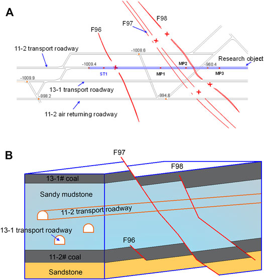
FIGURE 1. Location and geology engineering environment of research object. (A) Location of the 11-2 transport roadway. (B) Geological structure of the 11-2 transport roadway.
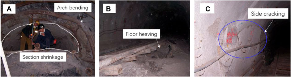
FIGURE 2. Large deformation characteristics. (A) Section shrinkage and arch bending. (B) Floor heaving. (C) Side cracking.
The section shape of the 11-2 transport roadway is a combination of a rectangle and a semicircle. The rectangle has a length of 5.2 m and height of 2.8 m, while the semicircle has a diameter of 5.2 m. The total length of this roadway is about 1,532 m, and it has been excavated over 1,000 m. As shown in Figure 1B, the 11-2 transport roadway is the roof of 11-2# coal and the floor of 13-1# coal, and most of its surrounding rock is sandy mudstone. Besides, the research roadway crosses the faults F97 and F98, which makes rocks relatively broken. Therefore, the research object belongs to a deep buried, soft, and broken roadway, which brings some unstable factors of the surrounding rock.
As shown in Figure 2, the 11-2 transport roadway has suffered a severely large deformation disaster since it was excavated. The large deformation characteristics, such as floor heaving, side cracking, steel arch bending, and section shrinkage, can be easily observed in the research roadway. These characteristics indicate that the original supporting process and method cannot control the deformation of the roadway in a reasonable extent, which may bring potential safety risks. It is necessary to take a reasonable support technique to maintain the stability of the roadway; otherwise the excavation rate will be affected.
Mechanical Property
According to rock matrix collected from the roadway, X-ray diffraction (XRD) analysis and uniaxial and triaxial compression tests were conducted to investigate the mechanical property of sandy mudstone.
It is commonly known that the mineral composition can decide the mechanical properties (i.e., strength, dilatability, softening property) of rock. As shown in Figure 3, XRD analysis results indicate that the sandy mudstone contains four minerals, including quartz (38.5%), kaolinite (26.1%), illite (12.8%), and montmorillonite (22.6%). Specifically, it can be found that kaolinite and montmorillonite each make up over 20% of the sandy mudstone.
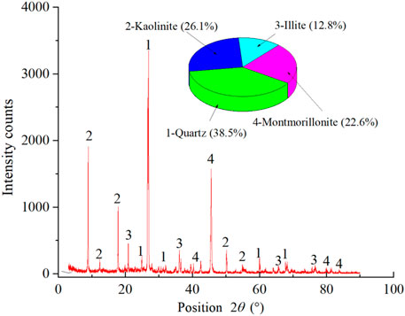
FIGURE 3. Minerals contents of the sandy mudstone by XRD measurement.
The rock blocks were collected from the roadway firstly, and then they were drilled into standard cylinder specimens with a height of 100 mm and a diameter of 50 mm, which satisfies the suggested methods of the International Society for Rock Mechanics (ISRM). Specifically, dry and saturated specimens were prepared by dry oven and vacuum deaeration, respectively. Figure 4 presents stress–strain curves of dry and saturated specimens. It is observed that uniaxial compressive strengths of sandy mudstone under air-dried and saturated conditions are 61.12 and 26.06 MPa, respectively. The tensile strength for dry and saturated specimens are 7.31 and 3.74 MPa, respectively. Therefore, the softening coefficient of surrounding rock is about 0.43, which means that the strength of sandy mudstone may decrease hugely after they absorbed water. Besides, triaxial compression tests indicate cohesion and internal friction angle are 9.48 MPa and 38.74°, respectively.
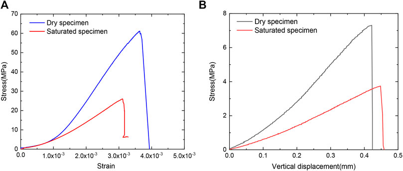
FIGURE 4. Stress–strain curves of dry and saturated specimens. (A) Uniaxial compression test. (B) Brazilian split test.
In Situ Stress
In situ stress is one of the most essential factors for roadway stability and support scheme selection. There are two methods, including hydraulic fracturing and borehole relief, which are widely used to obtain in situ stress (Haimson and Cornet, 2003). In this study, borehole relief method has been chosen to investigate the stress state of the 11-2 transport roadway.
As shown in Figure 1A, the in situ stress measurement site (ST1) is located at the 11-2 transport roadway with burial depth about 1,000 m. Figure 5 presents the test procedure, which is introduced briefly as follows: 1) Firstly, a horizontal big borehole with a diameter of approximately 130 mm, length of about 20 m, and direction of vertical side wall was drilled out using a rig. 2) Then, a small borehole with a diameter of 36 mm and length of about 350 mm was drilled out at the end of the big drilling hole for sensor installation. 3) Next, the sensor was pushed into the small hole and fixed with a binder. 4) At last, the rock core with the stress sensor was drilled out, and the strain of the sensor was collected during drilling.
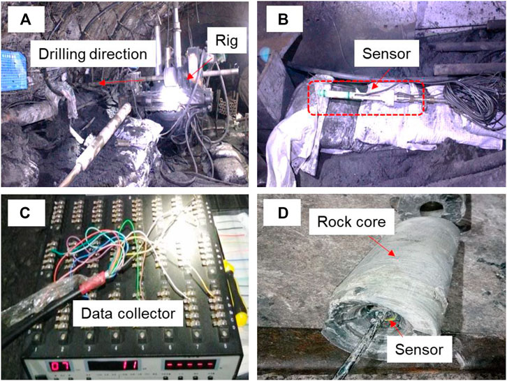
FIGURE 5. The test procedure of borehole relief method. (A) Drill the boreholes. (B) Sensor for stress measurement. (C) Data collector for the sensor. (D) Rock core drilled from borehole.
According to the relationship between the recovered strain of 12 sensors and relieving distance, combined with the strength of rock from the borehole, the in situ stress of this measurement point can be calculated. Results indicate that the maximum principal stress (σ1) is 35.49 MPa, minimum principal stress (σ3) is 16.09 MPa, and intermediate principal stress (σ2) is 20.11 MPa. Moreover, the maximum and minimum stresses along the horizontal direction (σH and σh) and the principal stress along vertical direction (σv) are 32.43, 25.38, and 24.91 MPa, respectively. According to the definition of coefficient of lateral pressure (σH/σy), it can be observed that the stress lateral pressure coefficient of the measurement point is about 1.30, which indicates that the maximum principal stress is along the horizontal direction and is mainly caused by geotectonic movement.
Large Deformation Disaster Mechanism
To investigate the large deformation disaster mechanism of the research roadway, a series of studies, including the above laboratory tests as well as numerical simulation, are conducted in this section. Many numerical methods have been used to simulate the process of crack initiation and propagation (Liu X. W et al., 2020). The two-dimensional Universal Discrete Element Code (UDEC) is commonly used to study the failure mechanisms of surrounding rock in the roadway (Tang et al., 2021). In this numerical approach, blocks are separated by fracture networks in the fractured rock mass, and these discrete blocks are connected by normal and shearing contacts. Once the load between two blocks over contact stiffness, tensile or shear failures will occur. As a result, the blocks may be disjoined and begin to move. Therefore, UDEC can simulate failure, movement, and rotation of blocks (Itasca, 2004), which are very suitable for investigation of the large deformation process and mechanism here.
UDEC Numerical Model
According to geology engineering environment shown in Figure 1, a numerical calculation model was established. As shown in Figure 6, this numerical model, which contains four different strata (i.e., sandstone, 11-2# coal, sandy mudstone, and 13-1# coal), is a square with dimension of 50 m × 50 m and a roadway located at the center of the model. The shape of the roadway is a straight wall with a semicircle at the top, and the width is 5.2 m, the height of the wall is 2.8 m, the and radius of the semicircle is 2.6 m. For layers of sandstone, 11-2# coal, and 13-1# coal, the joints were generated by two sets of fractures with angles of 0° and 90°. The layer of sandy mudstone has a height of 30 m. The upper part in scope of 10 m two set of fractures with angles of 0° and 90°, while the lower part was described by Voronoi blocks with average length of 1.5 m. Specifically, this average length decreases to 0.5 m around the roadway zone (dimension of 20 m × 20 m) due to the existence of a fractured zone.
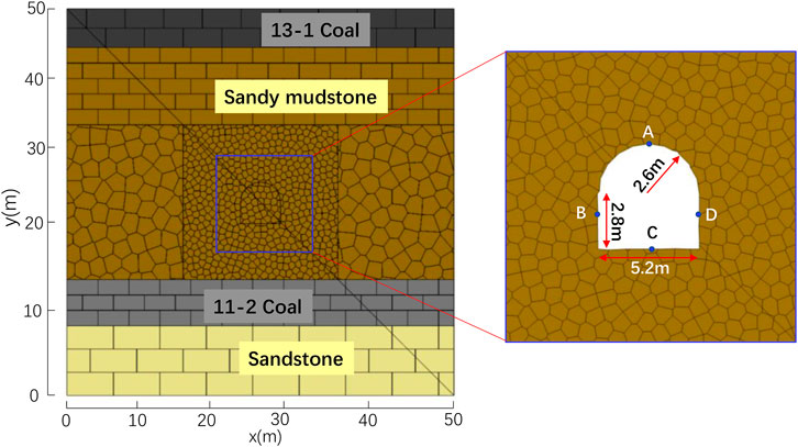
FIGURE 6. UDEC numerical model.
In this model, the vertical displacement is fixed at the base, while the horizontal displacement is fixed at the lateral sides. According to in situ stress measurement result, the horizontal and vertical stresses applied on the numerical model are 32.43 and 24.91 MPa, respectively. Four monitoring points around the surface of the roadway are set with coordination of A (x = 25.0 m, y = 27.6 m), B (x = 22.4 m, y = 23.6 m), C (x = 25.0 m, y = 22.2 m), and D (x = 27.6 m, y = 23.6 m) to monitor the deformation characteristics. Specifically, only y-direction displacement is monitored for points A and C, while x-direction displacement is monitored for points B and D.
There are macro-parameters of intact rock blocks and micro-parameters of contacts between blocks in the UDEC model. According to laboratory tests and numerical calibration tests, the mechanical parameters of the model are listed in Table 1. In Table 1,
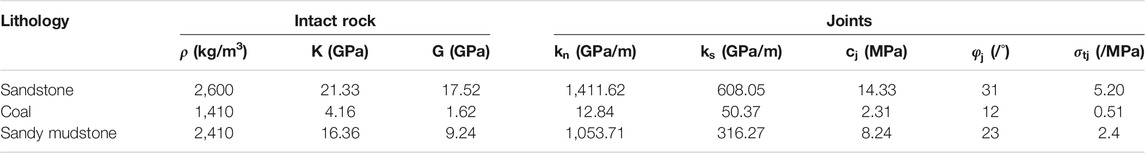
TABLE 1. Parameters of UDEC model.
Simulation Results
Figure 7 displays y-displacement, shear stress, and the maximum principal stress distribution around the roadway at different time step. For the y-displacement, as shown in Figure 7A, there is a clear boundary between the roof and floor for time step 10,000. The y-displacement is negative for the rock above the boundary, while this value is positive below the boundary line. The negative displacement indicates the roof settlement, and the maximum y-displacement at the roof is about 265.6 mm due to the fractured rock falling. The positive displacement is mainly caused by floor heave, and the maximum positive y-displacement concentrates on the central part of the floor, which is about 51.9 mm; when the time step increases to 100,000, the y-displacement distribution is totally different. As shown in Figure 7B, y-displacement is concentrated around the roadway, and the changing of y-displacement is not obvious for the area far away from the roadway. Similarly, the maximum roof settlement is about 0.8 m, while the floor heave is 1.08 m approximately.
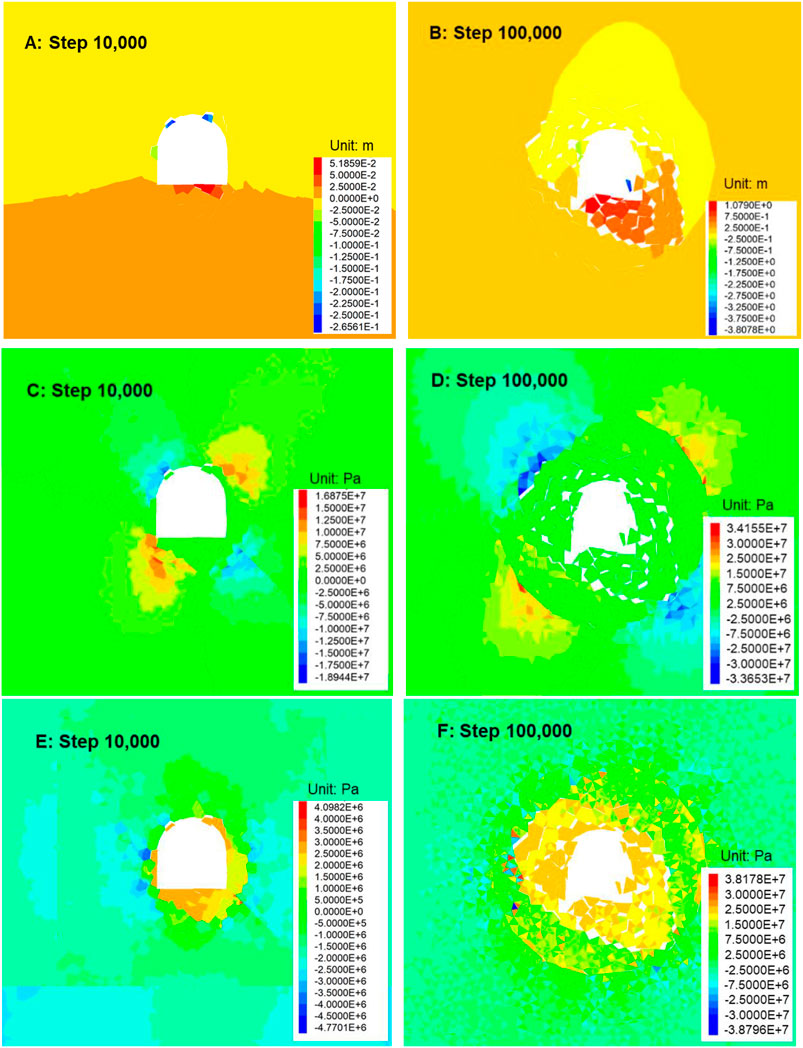
FIGURE 7. Distribution of displacement and stress at different steps. (A,B) Displacement distribution of y-direction. (C,D) Shear stress distribution. (E,F) The maximum principal stress distribution.
For the stress distribution, as shown in Figures 7C,D the shear stress is mainly concentrated around the roof and floor corners when time step is 10,000 and the maximum shear stress is about 16.8 MPa. At this stage, the maximum principal stress distribution is around the roadway with depth of 1.5 m approximately (Figure 7E). When the time step increases to 100,000, the surrounding rock becomes more broken, and a crack propagates in the deep part of the surrounding rock gradually. Similarly, as shown in Figures 7D,F, the range of shear stress and the maximum principal stress concentration area gradually expands.
Figure 8 shows the crack initiation, propagation, coalescence, and failure process of the surrounding rock during calculation. For time step 10,000, the surrounding rock already has a series of cracks that exist, and the maximum cracking depth at the right side and bottom of the roadway are 1.91 and 2.72 m. Besides, most of these newly generated cracks are independent and discrete. Once these discrete cracks coalesce together, a fractured block may be formed. As illustrated in Figure 8A, the newly formed broken rock causes the failure of the roadway. The failure phenomenon including block falling and side cracking can be observed at this stage. Furthermore, a more severe failure mode can be detected at time step 100,000. As shown in Figure 8B, the maximum cracking depth at the right side and bottom of the roadway increases to 4.96 and 5.03 m, respectively. Two broken zone (areas inside the blue lines) around the fault can be easily distinguished. The typical large deformation disaster characteristics, such as section shrinkage, floor heaving, and side cracking, can all be observed.
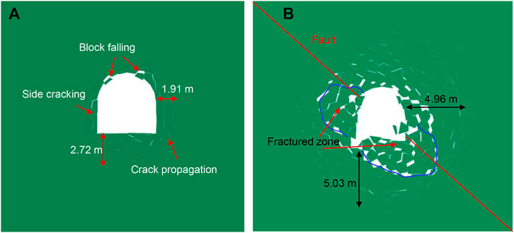
FIGURE 8. Roadway failure process. (A) Time step 10,000. (B) Time step 100,000.
Large Deformation Mechanism
According to the laboratory tests, in situ geo-stress measurement, and numerical simulation, the large deformation mechanism for the deep roadway in the broken fault zone can be summarized as follows.
Firstly, the XRD test result indicates that the main clay minerals of the surrounding rock are kaolinite, illite, and montmorillonite. After absorbing water, montmorillonite and illite may show the characteristics of swelling and softening, respectively. As a result, the volume of rock sample will increase, while the strength may decrease sharply. The uniaxial compression test results verified this point. The results show that the softening coefficient of the surrounding rock is about 0.43. Therefore, the lower strength of the surrounding rock and easy-to-soften property is an immanent cause for a large deformation disaster.
Secondly, a high in situ geo-stress exists in the surrounding rock. Tests results indicate that the maximum stress along the horizontal direction (σH) and along the vertical direction (σv) are 32.43 and 24.91 MPa. Besides, the tectonic movement around this area combined with blasting excavation made the surrounding rock quite broken. The broken and fractured rock masses can easily cause a large deformation behavior under a high geo-stress, which is the is external inducement for a large deformation disaster.
Finally, the numerical simulation reproduced the large deformation process of the research roadway. Considering the soft and broken rock under high stress condition, the final failure mode is shown in Figure 9A. The rock blocks are connected by a lower weak cementation between joints initially. However, these cementations in the joints will gradually fail due to excavation. As shown in Figure 9A, four main failure modes, including block opening, sliding, movement, and rotation, can be observed during calculation. The opened rock blocks are separated from each other, and then they can slide together or move freely. The rock block at the surface of the roadway moves and falls into the roadway, and then those blocks in the deep part begins to open and move forward.
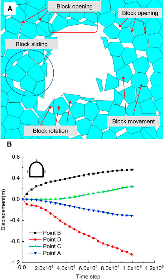
FIGURE 9. The final simulation results. (A) The final failure mode of research roadway. (B) The displacement of monitoring points without support.
As shown in Figure 9B, the x-direction displacement of points B and D are 0.56 and 1.06 m, while the y-direction displacement of points A and C are 0.31 and 0.24 m. The curves in Figure 14 also indicate that these deformations do not show a convergent tendency. Therefore, these continuous and uninterrupted behaviors of opening, moving, and rotation are the main reason of the large deformation.
Large Deformation Control Technique
Stages and Combination Control Method
According to the analysis of large deformation mechanism listed above, a control technique named SCCM has been proposed here. In this method, there are two progressive supporting stages, and these two different stages should be jointly implemented in a certain order.
As shown in Figure 10, the primary support stage (red lines in Figure 10A) consists of the following processes: firstly, eight prestressed anchor bolts with a length of 2.5 m and space of 1.4 m are arranged; then, shotcrete with a depth of 50–100 mm is sprayed on the surface of the roadway; finally, grouting with hole depths of 1.5 and 5.0 m are implemented step by step. After the primary support stage, the secondary support stage (purple lines in Figure 10A), which contains seven cables with a length of 6.3 m and space of 2.0 m, are arranged.
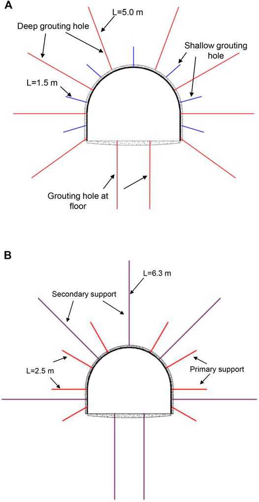
FIGURE 10. The schematic diagram for SCCM technique. (A) Distribution of grouting holes. (B) Distribution of bolts and cables.
Numerical Simulation Analysis
In order to investigate the control effect of SCCM technique, two numerical cases were conducted in this section. In case 1, only the primary support stages are used after roadway excavation, while both the primary and secondary stages are considered in case 2. The computational model is the same as the UDEC numerical model, and numerical simulation results are shown in Figure 11.
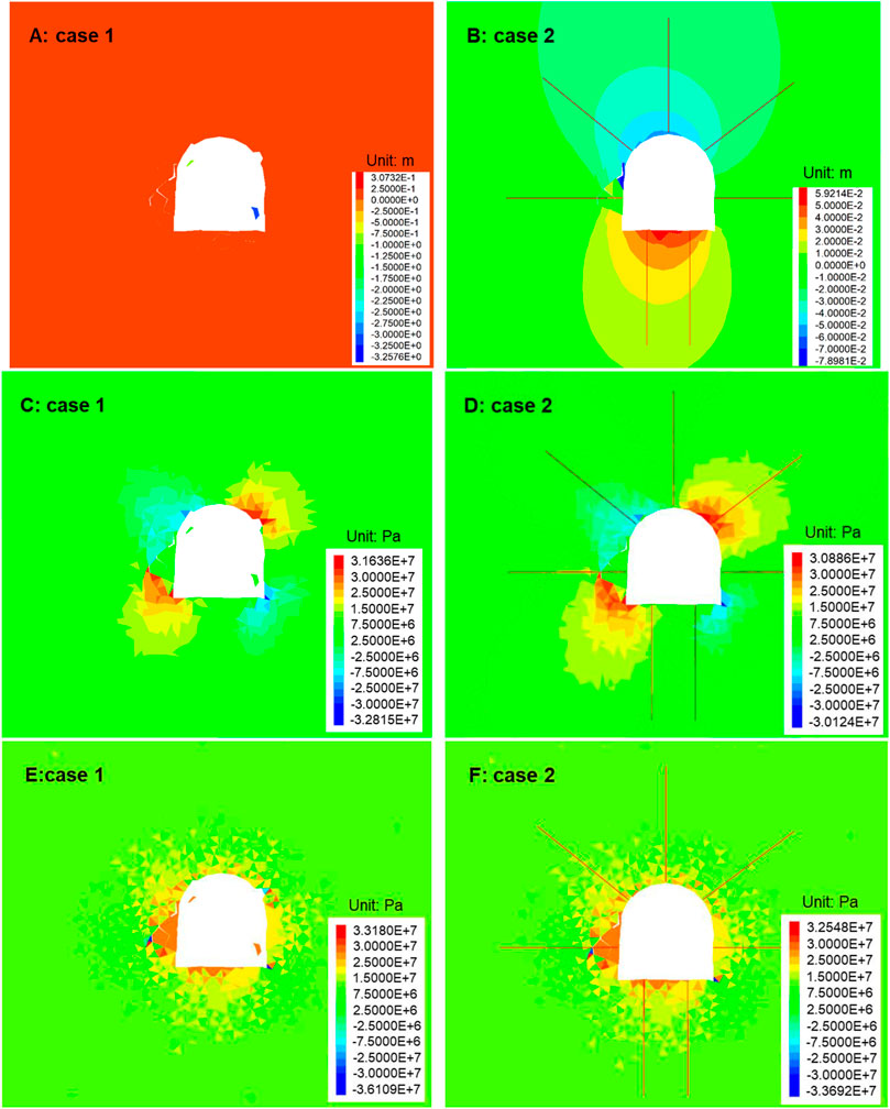
FIGURE 11. Numerical simulation results of case 1 and case 2. (A,B) Y-displacement distribution. (C,D) Shear stress distribution. (E,F) The maximum principal stress distribution.
As shown in Figures 11A,B, the y-direction displacement is larger than that of case 2. There are two small rock blocks that dissociated from the roof and fell into the roadway for case 1. For case 2, the maximum y-displacement is concentrated on the central part of the floor and roof, which are 59.2 and 78.9 mm, approximately. However, for the stress distribution, they are almost the same between case 1 and case 2 no matter the shear stress or the maximum principal stress. The difference is that the stress has a tiny decrease, while the distribution span extends a little for case 2 compared with case 1, which indicates that the secondary support cables transfer the stress from surface of the roadway to the deep part of the surrounding rock.
The failure mode was also investigated. As shown in Figure 12, after the SCCM technique was implemented, there are no blocks sliding, movement, or rotation during simulation, and only block opening has been observed. For the bottom of the roadway, only several tiny cracks initiated and propagated with a depth of 0.5 m approximately. The left side of the surrounding rock has some opening block and has a tendency of side cracking. However, this disaster has been controlled finally because of the effect of the cables. Besides, no evident cracks can be found at the top and right side of the roadway, which indicates that the SCCM technique can stop the failure of the surrounding rock.
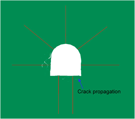
FIGURE 12. Final failure mode of roadway after SCCM technique was implemented.
Furthermore, the calculated displacements of different monitoring points of case1 and case 2 are shown in Figure 13. Compared with Figure 9B, it is very clear that the maximum x-displacement of point B for no support is about 560.2 mm, while this value decreases to 107.4 and 50.9 mm for case 1 and case 2, respectively. Similarly, the maximum displacements in the x-direction for point D are 1,059.4, −51.5, and −23.8 mm for no support, for case 1, and for case 2, respectively. Besides, some tiny failure and deformation are still observed in the left side wall from Figure 12, which is mainly because of the existence of a sliding plane cut from the fault. These deformations within the acceptable range and numerical results here indicate that SCCM method can control displacement effectively.
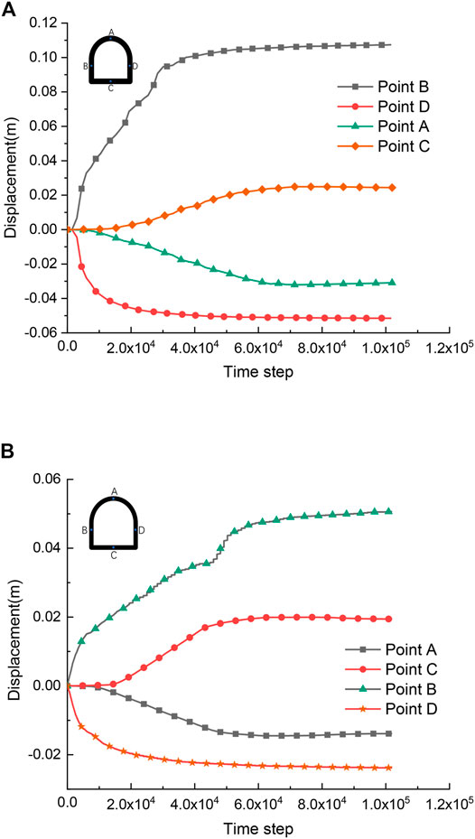
FIGURE 13. Displacement of monitoring points. (A) Case 1. (B) Case 2.
In Situ Deformation Monitoring
As shown in Figure 1A, three monitoring points, namely, MP1, MP2, and MP3, were set in the research roadway to verify the proposed SCCM technique. The monitoring devices were installed on both side walls of the roadway to obtain convergence deformation of the two side walls. As shown in Figure 14A, two monitoring piles were fixed on both sides of the roadway. Then, the deformation was measured by a convergence gauge (3WRM-3), which has a precision of 0.01 mm. The monitoring results indicated that the displacements increased sharply during the first several days. Then, the increasing rate decreases gradually till the 21st, and 34th day for MP2 and MP3, respectively.
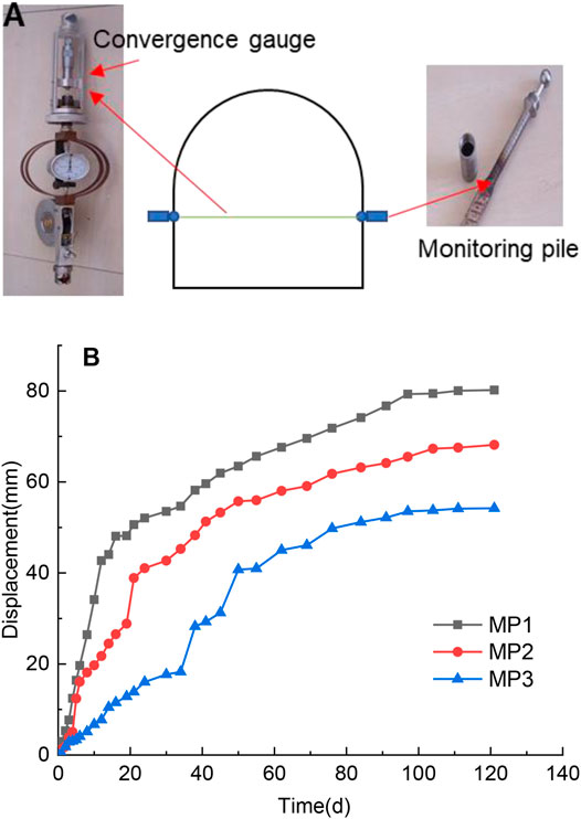
FIGURE 14. In situ deformation monitoring. (A) Methods and facilities. (B) Relation curves between displacement and time.
At that moment, the effect of primary support faded away, and cracks and failure arose in the surrounding rock. After implement of the secondary support stage, the deformation rate began to slow down, and the final deformation rates were 0.045, 0.051, and 0.026 mm/day for MP1, MP2, and MP3, respectively. Besides, this very low deformation rate lasted more than 20 days, which indicates this roadway was already stable. The final convergences of the side walls were 80.91, 68.15, and 54.21 mm for MP1, MP2, and MP3, respectively. These values are very close to the numerical result (about 74.7 mm), which also validates the effectiveness of the numerical method.
Conclusion
Considering the large deformation disaster of deep roadways in fault fractured zones, the mechanism of large deformation has been studied firstly. Then, SCCM technique has been proposed to control the large deformation in the present work. The main contributions are listed as follows:
(1) According to engineering geological survey, the 11-2 transport roadway encountered two faults named F97 and F98. After excavation of the roadway, large deformation behaviors, such as floor heaving, side cracking, steel arch bending, and section shrinkage, can be easily observed, which indicates the present support frame cannot maintain the stability of the roadway.
(2) Combined with laboratory tests, in situ stress measurement, and numerical simulation, the large deformation mechanism of the research roadway has been observed. The characteristics of lower strength of and easy to soften property of the surrounding rock is an immanent cause, while high geo-stress is an external inducement of large deformation disaster. Based on these, continuous and uninterrupted behaviors of opening, moving, and rotation of rock blocks finally caused a large deformation disaster.
(3) A control technique named SCCM has been proposed to solve the large deformation disaster. Two steps, named primary and secondary support stages, are included in this method. Numerical analysis and in situ monitoring results indicate that the SCCM technique can stop the failure and control the displacement of the surrounding rock effectively.
Data Availability Statement
The raw data supporting the conclusion of this article will be made available by the authors, without undue reservation.
Author Contributions
BL and YL were involved in the final development of the project and manuscript preparation. XL wrote the manuscript draft. JC analyzed the data. XH and YZ carried out the field investigation. All authors: corrections, modifications, and final acceptance.
Funding
This work was supported by the National Natural Science Foundation of China (Nos: 41807249, 51974289) and Natural Science Foundation of Anhui Province (Grant No: 2108085ME155).
Conflict of Interest
YL was employed by the Ping′an Mining Engineering Technology Research Institute Co., Ltd.
The remaining authors declare that the research was conducted in the absence of any commercial or financial relationships that could be construed as a potential conflict of interest.
Publisher’s Note
All claims expressed in this article are solely those of the authors and do not necessarily represent those of their affiliated organizations, or those of the publisher, the editors and the reviewers. Any product that may be evaluated in this article, or claim that may be made by its manufacturer, is not guaranteed or endorsed by the publisher.
References
Bao, L. H. (2014). In Situ stress Measurement and Surrounding Rock Stability Analysis of the Gaoligong Mountain Tunnel. Amm 501-504, 1766–1773. doi:10.4028/www.scientific.net/amm.501-504.1766
Deng, P., Liu, Q., Huang, X., Liu, Q., Ma, H., and Li, W. (2021). Acquisition of normal Contact Stiffness and its Influence on Rock Crack Propagation for the Combined Finite-Discrete Element Method (FDEM). Eng. Fracture Mech. 242 (2), 107459. doi:10.1016/j.engfracmech.2020.107459
Du, C., Cao, P., Chen, Y., Liu, J., Zhao, Y., and Liu, J. (2017). Study on the Stability and Deformation of the Roadway Subjected to High In-Situ Stresses. Geotech. Geol. Eng. 35 (4), 1–14. doi:10.1007/s10706-017-0197-9
Feng, F., Chen, S., Wang, Y., Huang, W., and Han, Z. (2021). Cracking Mechanism and Strength Criteria Evaluation of Granite Affected by Intermediate Principal Stresses Subjected to Unloading Stress State. Int. J. Rock Mech. Mining Sci. 143, 104783. doi:10.1016/j.ijrmms.2021.104783
Guo, Z., Wang, J., and Zhang, Y. (2015). Failure Mechanism and Supporting Measures for Large Deformation of Tertiary Deep Soft Rock. Int. J. Mining Sci. Tech. 25 (1), 121–126. doi:10.1016/j.ijmst.2014.11.002
Haimson, B. C., and Cornet, F. H. (2003). ISRM Suggested Methods for Rock Stress Estimation-Part 3: Hydraulic Fracturing (HF) And/or Hydraulic Testing of Pre-existing Fractures (HTPF). Int. J. Rock Mech. Mining Sci. 40, 1011–1020. doi:10.1016/j.ijrmms.2003.08.002
He, L., An, X. M., Zhao, X. B., and Zhao, Z. Y. (2013). Investigation on Strength and Stability of Jointed Rock Mass Using Three-Dimensional Numerical Manifold Method. Int. J. Numer. Anal. Meth. Geomech. 37 (14), 2348–2366. doi:10.1002/nag.2147
Hoek, E., and Guevara, R. (2009). Overcoming Squeezing in the Yacambú-Quibor Tunnel, Venezuela. Rock Mech. Rock Eng. 42, 389–418. doi:10.1007/s00603-009-0175-5
Huang, B. X., Zhang, N., Jing, H. W., Kan, J. G., Meng, B., Li, N., et al. (2020). Large Deformation Theory of Rheology and Structural Instability of the Surrounding Rock in Deep Mining Roadway. J. China Coal Soc. 45 (3), 911–926.
Kang, H. P., Lin, J., and Fan, M. J. (2015). Investigation on Support Pattern of a Coal Mine Roadway within Soft Rocks - a Case Study. Int. J. Coal Geology. 140, 31–40. doi:10.1016/j.coal.2015.01.003
Kang, H. P. (2016). Sixty Years Development and Prospects of Rock Bolting Technology for Underground Coal Mine Roadways in China. J. China Univ. Technol. 45, 1071–1081.
Kang, Y., Liu, Q., Gong, G., and Wang, H. (2014). Application of a Combined Support System to the Weak Floor Reinforcement in Deep Underground Coal Mine. Int. J. Rock Mech. Mining Sci. 71, 143–150. doi:10.1016/j.ijrmms.2014.03.017
Kang, Y., Liu, Q., Xi, H., and Gong, G. (2018). Improved Compound Support System for Coal Mine Tunnels in Densely Faulted Zones: a Case Study of China's Huainan Coal Field. Eng. Geology. 240, 10–20. doi:10.1016/j.enggeo.2018.04.006
Li, G., Ma, F., Guo, J., Zhao, H., and Liu, G. (2020). Study on Deformation Failure Mechanism and Support Technology of Deep Soft Rock Roadway. Eng. Geology. 264, 105262. doi:10.1016/j.enggeo.2019.105262
Li, Z., Liu, H., Dun, Z., Ren, L., and Fang, J. (2020). Grouting Effect on Rock Fracture Using Shear and Seepage Assessment. Construction Building Mater. 242 (5), 118131. doi:10.1016/j.conbuildmat.2020.118131
Liu, D. J., Zuo, J. P., Wang, J., Zhang, T. L., and Liu, H. Y. (2020). Large Deformation Mechanism and concrete-filled Steel Tubular Support Control Technology of Soft Rock Roadway-A Case Study. Eng. Fail. Anal. 116, 104721. doi:10.1016/j.engfailanal.2020.104721
Liu, X., Chen, H., Liu, Q., Liu, B., and He, J. (2022). Modelling Slurry Flowing and Analyzing Grouting Efficiency under Hydro-Mechanical Coupling Using Numerical Manifold Method. Eng. Anal. Boundary Elem. 134, 66–78. doi:10.1016/j.enganabound.2021.09.030
Liu, X., Hu, C., Liu, Q., and He, J. (2021). Grout Penetration Process Simulation and Grouting Parameters Analysis in Fractured Rock Mass Using Numerical Manifold Method. Eng. Anal. Boundary Elem. 123, 93–106. doi:10.1016/j.enganabound.2020.11.008
Liu, X., Liu, Q., Liu, B., Zhu, Y., and Zhang, P. (2019). Failure Behavior for Rocklike Material with Cross Crack under Biaxial Compression. J. Mater. Civ. Eng. 31 (2), 06018025. doi:10.1061/(asce)mt.1943-5533.0002540
Liu, X. W., Liu, Q. S., He, J., and Yu, F. (2020). Numerical Simulation of Cracking Process in Rock Mass under the Coupled Thermo-Mechanical Condition. Int. J. Comp. Meth. 17 (9), 1950065. doi:10.1142/s0219876219500658
Seo, H.-J., Choi, H., and Lee, I.-M. (2016). Numerical and Experimental Investigation of Pillar Reinforcement with Pressurized Grouting and Pre-stress. Tunnelling Underground Space Tech. 54, 135–144. doi:10.1016/j.tust.2015.10.018
Tan, X., Chen, W., Liu, H., Chan, A. H. C., Tian, H., Meng, X., et al. (2017). A Combined Supporting System Based on Foamed concrete and U-Shaped Steel for Underground Coal Mine Roadways Undergoing Large Deformations. Tunnelling Underground Space Tech. 68, 196–210. doi:10.1016/j.tust.2017.05.023
Tang, B., Yeboah, M., Cheng, H., Tang, Y., Yao, Z., Wang, C., et al. (2021). Numerical Study and Field Performance of Rockbolt Support Schemes in TBM-Excavated Coal Mine Roadways: A Case Study. Tunnelling Underground Space Tech. 115, 104053. doi:10.1016/j.tust.2021.104053
Zhao, C., Li, Y., Liu, G., and Meng, X. (2020). Mechanism Analysis and Control Technology of Surrounding Rock Failure in Deep Soft Rock Roadway. Eng. Fail. Anal. 115, 104611. doi:10.1016/j.engfailanal.2020.104611
Keywords: large deformation, mechanism, control technique, deep roadway, faulted zone
Citation: Liu X, Chen J, Liu B, Luo Y, Zhu Y and Huang X (2022) Large Deformation Disaster Mechanism and Control Technique for Deep Roadway in Faulted Zone. Front. Earth Sci. 10:826661. doi: 10.3389/feart.2022.826661
Received: 01 December 2021; Accepted: 18 January 2022;
Published: 18 February 2022.
Edited by:
Zetian Zhang, Sichuan University, ChinaReviewed by:
Yuantian Sun, China University of Mining and Technology, ChinaZhizhen Zhang, China University of Mining and Technology, China
Chao Yuan, Hunan University of Science and Technology, China
Copyright © 2022 Liu, Chen, Liu, Luo, Zhu and Huang. This is an open-access article distributed under the terms of the Creative Commons Attribution License (CC BY). The use, distribution or reproduction in other forums is permitted, provided the original author(s) and the copyright owner(s) are credited and that the original publication in this journal is cited, in accordance with accepted academic practice. No use, distribution or reproduction is permitted which does not comply with these terms.
*Correspondence: Bin Liu, liubin@whrsm.ac.cn; Xing Huang, xhuang@whrsm.ac.cn